9. Triple Play Enhanced Subscriber Management
9.1. In This Section
This section describes features which provide Enhanced Subscriber Management functions for Triple Play services.
Topics in this section include:
9.2. Uniform RADIUS Server Configuration
9.2.1. RADIUS Server Configuration
The following two configuration methods co-exist but are mutually exclusive:
9.2.1.1. Uniform RADIUS Server Configuration (Preferred)
This configuration method is preferred as it can be re-used amongst multiple applications (Subscriber authentication and accounting, L2TP tunnel accounting, WLAN gateway RADIUS proxy,) and enables additional functionality not available in the legacy configuration method. For example:
- A RADIUS server policy operational state can be controlled by reception of accounting on/off responses.
- Buffering of accounting messages: When all servers in a radius-server-policy are unreachable, it is possible to buffer the acct-stop and acct-interim-update messages for up to 25 hours. When a RADIUS server becomes reachable again then the messages in the buffer are retransmitted.
- A configurable hold down time for accounting servers that are marked down and during which no new communication attempts will be made (hold-down-time).
- A configurable maximum number of outstanding RADIUS requests for accounting servers (pending-requests-limit).
- Increased retry and timeout values for unsuccessful RADIUS communication.
- Enhanced RADIUS server statistics
- IPv6 RADIUS server
| Note: A RADIUS server is marked down if it detects a number of consecutive timeouts independent of transaction-id or origin of request. |
Where a number of consecutive timeouts is defined by the number of retries configured below the radius-server-policy servers.
The default number of retries is 3, meaning 1 initial try and 2 retries.
If, for example, the RADIUS server has “2 timeouts, 1 reply, 1 timeouts”, whereby the timeouts are originated for the same host, the server is not marked down since intermediate replies were received.
To attach a RADIUS server policy to an authentication policy:
For example,
Note:
|
To attach a RADIUS server policy to a RADIUS accounting policy:
For example:
| Note: To avoid conflicts, the following CLI commands are ignored in the RADIUS accounting policy when a radius-server-policy is attached:
|
To configure the RADIUS servers in a RADIUS server policy:
For example:
To configure the RADIUS servers in the routing instance:
- In the Base routing instance: config>router>radius-server.
- In a VPRN routing instance: config>service>vprn 10>radius-server.
- In the management routing instance (out of band): config>router management>radius-server.
For example:
| Note: To configure RADIUS CoA servers for use in Enhanced Subscriber Management, the server must be configured in the corresponding routing instance with the accept-coa command enabled. |
9.2.1.2. Legacy RADIUS Server Configuration
| Note: It is recommended to migrate to the uniform RADIUS server configuration as described above to have additional functionality enabled. |
To configure a RADIUS server in an authentication policy:
| Note: In legacy RADIUS server configuration, to configure RADIUS CoA servers for use in Enhanced Subscriber Management, the server must be configured in the authentication policy with the accept-authorization-change command enabled. A CoA only server can be configured with the optional coa-only flag. |
To configure a RADIUS server in a RADIUS accounting policy:
9.3. RADIUS Authentication of Subscriber Sessions
This section describes the Nokia router acting as a Broadband Subscriber Aggregator (BSA).
| Note: In the TPSDA solutions, the Nokia 5750 Subscriber Services Controller (SSC) serves as the policy manager, DHCP and RADIUS server. |
In this application, one of the required functions can be to authenticate users trying to gain access to the network.While sometimes the DHCP server (an SSC) can perform authentication, in most cases a RADIUS server (an SSC) is used to check the customer's credentials.
| Note: Refer to section DHCP Management for an explanation of DHCP and DHCP Snooping for an explanation of DHCP snooping. |
For information about the RADIUS server selection algorithm, refer to the Security chapter in the OS System Management Guide.
If authentication is enabled, the router will temporarily hold any received DHCP discover message and will send a access-request message to a configured RADIUS server containing the client's MAC address and/or Circuit-ID (from the Option 82 field) as the user name. If and when access is granted by the RADIUS server, the router will then forward or relay the DHCP discover message to the DHCP server and thus allow an IP address to be assigned. If the RADIUS authentication request is denied, the DHCP message is dropped and an event is generated.
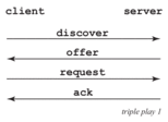
A typical initial DHCP scenario (after client bootup) is shown in Figure 63.
Figure 63: Initial DHCP Scenario
But, when the client already knows its IP address (when an existing lease is being renewed), it can skip straight to the request/ack phase, as shown in Figure 63.
Figure 64: DHCP Scenario with Known IP Address
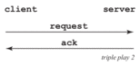
In the first scenario, the DHCP discover triggers an authentication message to RADIUS and the DHCP request also triggers RADIUS authentication. The previous reply is cached for 10 seconds, the second DHCP packet will not result in a RADIUS request. In the second scenario, the DHCP request triggers an authentication message to RADIUS.
If the optional subscriber management authentication policy re-authentication command is enabled, DHCP authentication is performed at every DHCP lease renew request. Only dynamic DHCP sessions are subject to remote authentication. Statically provisioned hosts are not authenticated.
9.3.1. RADIUS Authentication Extensions
This section describes an extension to RADIUS functionality in the subscriber management context. As part of subscriber host authentication, RADIUS can respond with access-response message, which, in the case of an accept, can include several RADIUS attributes (standard and vendor-specific) that allow proper provisioning of a given subscriber-host.
Change-of-Authorization (CoA) messages as defined by RFC 3576, Dynamic Authorization Extensions to Remote Authentication Dial In User Service (RADIUS), are supported. The goal of CoA messages is to provide a mechanism for “mid-session change” support through RADIUS.
9.3.1.1. Triple Play Network with RADIUS Authentication
Figure 65: Triple Play Aggregation Network with RADIUS-Based DHCP Host Authentication
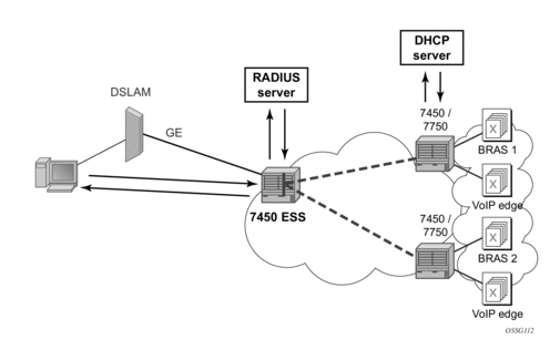
Figure 65 shows a flow of RADIUS authentication of DHCP hosts in the triple play aggregation environment. Besides granting the authentication of given DHCP host, the RADIUS server can include RADIUS attributes (standard and/or Vendor-Specific Attributes (VSAs)) which are then used by the network element to provision objects related to a given DHCP host.
RADIUS is a distributed client/server concept that is used to protect networks against unauthorized access. In the context of the router’s subscriber management in TPSDA, the RADIUS client running on nodes sends authentication requests to the SSC.
RADIUS can be used to perform three distinct services:
- Authentication determines whether or not a given subscriber-host is allowed to access a specific service.
- Authorization associates connection attributes or characteristics with a specific subscriber host.
- Accounting tracks service use by individual subscribers.
The RADIUS protocol uses “attributes” to describe specific authentication, authorization and accounting elements in a user profile (which are stored on the RADIUS server). RADIUS messages contain RADIUS attributes to communicate information between network elements running a RADIUS client and a RADIUS server.
RADIUS divides attributes into two groups, standard attributes and Vendor-Specific Attributes (VSAs). VSA is a concept allowing conveying vendor specific configuration information in a RADIUS messages, discussed in RFC 2865, Remote Authentication Dial In User Service (RADIUS). It is up to the vendor to specify the exact format of the VSAs. Nokia-specific VSAs are identified by vendor-id 6527.
9.3.2. RADIUS Authorization Extensions
The following sections define different functional extensions and list relevant RADIUS attributes.
Basic Provisioning of Authentication Extensions
In order to comply with RFC 4679, DSL Forum Vendor-Specific RADIUS Attributes, the software includes the following attributes in the authentication-request message:
- agent-circuit-id (as defined by DSL forum)
- agent-remote-id (as defined by DSL forum)
The following attributes can also be included if configured and provided by downstream equipment:
- actual-data-rate-upstream
- actual-data-rate-downstream
- minimum-data-rate-upstream
- minimum-data-rate-downstream
- access-loop-encapsulation
When the node is configured to insert (or replace) Option 82, the above mentioned attributes will have the content after this operation has been performed by the software.
In addition, the following standard RADIUS attributes will be included in authentication request messages (subject to configuration):
- NAS-identifier — string containing system-name
- NAS-port-id
- NAS-port-type — Values: 32 (null encap), 33 (dot1q), 34 (qinq), 15 (DHCP hosts), specified value (0 — 255)
- MAC-address (Nokia VSA 27)
- dhcp-vendor-class-id (Nokia VSA 36)
- calling-station-id
These will only be included in the access-request if they have been configured.
In order to provide the possibility to push new policies for currently active subscribers, the routers support commands to force re-authentication of the given subscriber-host. After issuing such a command, the router will send a DHCP force-renew packet, which causes the subscriber to renew its lease (provided it supports force-renew). The DHCP request and ACK are then authenticated and processed by the routers as they would be during a normal DHCP renew.
9.3.2.1. Calling-Station-ID
A calling-station-id can be configured at SAP level and can be included in the RADIUS authentication and accounting messages. This attribute is used in legacy BRAS to identify the user (typically phone number used for RAS connection). In the broadband networks this was replaced by circuit-id in Option 82. However, the Option 82 format is highly dependent on access-node vendor, which makes interpretation in management servers (such as RADIUS) troublesome. Some operators use the calling-station-id attribute as an attribute indicating the way the circuit-id should be interpreted. The calling-station-id attribute can be configured as a string which will be configured on the SAP. It can also be configured to use the sap-id, remote-id or mac-address.
9.3.2.2. Subscriber Session Timeout
To limit the lifetime of a PPP session or DHCPv4 host to a fixed time interval, a timeout can be specified from RADIUS. By default, a PPP session or DHCPv4 host has no session timeout (infinite).
For PPP sessions, a session-timeout can be configured in the ppp-policy. A RADIUS specified session-timeout overrides the CLI configured value.
When the session timeout expires a PPP session is terminated and a DHCPv4 host deleted. For a DHCPv4 host, a DHCP release message is also sent to the server.
The following two attributes can be used in RADIUS Access-Accept and CoA messages to limit the PPP session or DHCPv4 host session time (Table 52):
Table 52: Subscriber Session Timeout
Attribute ID | Attribute Name | Type | Limits | Purpose and Format |
27 | Session-Timeout | integer | 2147483647 seconds | 0 = infinite (no session-timeout) [1 to 2147483647] in seconds For example: Session-Timeout = 3600 |
26-6527-160 | Alc-Relative-Session-Timeout | integer | [0 to 2147483647] seconds | 0 = infinite (no session-timeout) [1 to 2147483647] in seconds For example: Alc-Relative-Session-Timeout = 3600 |
When specified in a RADIUS Access-Accept message, both attributes specify an absolute value for session timeout. When specified in a RADIUS CoA message, attribute [26-6527-160] Alc-Relative-Session-Timeout specifies a relative session timeout value in addition to the current session time while attribute [27] Session-Timeout specifies an absolute session timeout value. If the current session time is greater than the received Session-Timeout, a CoA NAK is sent with error cause “Invalid Attribute Value (407)”.
Only one of the above attributes to specify a session timeout can be present in a single RADIUS message. An event is raised when both are specified in a single message.
The output of the show service id <service-id> ppp session detail CLI command contains following fields related to session timeout for PPP sessions:
- Up Time: the PPP session uptime
- Session Time Left: the remaining time before the session is terminated
- RADIUS Session-TO: the RADIUS received session timeout value.
The output of the “show service id <service-id> dhcp lease-state detail” CLI command contains following fields related to session timeout for DHCPv4 hosts:
- Up Time: the DHCPv4 host uptime
- Remaining Lease Time: the remaining time before the lease expires in the DHCP server. The client should renew its lease before this time.
- Remaining SessionTime: the remaining time before the DHCPv4 host is deleted
- Session-Timeout: the DHCPv4 host is deleted when its uptime reaches the Session-Timeout value.
- Lease-Time: the lease time specified by the DHCPv4 server
| Note: In a radius-proxy scenario or when a DHCPv4 host is created with a RADIUS CoA message, the RADIUS attribute [26-6527-174] Alc-Lease-Time attribute must be used to specify the lease time. If the [26-6527-174] Alc-Lease-Time is not present in these scenarios, then the RADIUS attribute [27] Session-Timeout is interpreted as DHCPv4 lease time. |
9.3.2.2.1. Domain Name in Authentication
In many networks, the user name has specific meaning with respect to the domain (ISP) where the user should be authenticated. In order to identify the user correctly, the user name in an authentication-request message should contain a domain-name. The domain-name can be derived from different places. In PPPoE authentication the domain name is given by the PPPoE client with the user name used in PAP or CHAP authentication. For DHCP hosts similar functionality is implemented by a “pre-authentication” lookup in a local user database before performing the RADIUS request.
For example, it can be derived from option60 which contains the vendor-specific string identifying the ISP the set-box has been commissioned by.
To append a domain name to a DHCP host, the following configuration steps should be taken:
- Under the (group or IP) interface of the service, a local user database should be configured in the DHCP node and no authentication policy should be configured.
- In the local user database, there should be a host entry containing both the domain name to be appended and an authentication policy that should be used for RADIUS authentication of the host. The host entry should contain no other information needed for setting up the host (IP address, ESM string), otherwise the DHCP request will be dropped.
- In the authentication policy, the user-name-format command should contain the parameter append domain-name.
9.3.2.3. RADIUS Reply Message for PPPoE PAP/CHAP
The string returned in a [18] Reply-Message attribute in a RADIUS Access-Accept is passed to the PPPoE client in the CHAP Success or PAP Authentication-Ack message.
The string returned in a [18] Reply-Message attribute in a RADIUS Access-Reject is passed to the PPPoE client in the CHAP Failure or PAP Authentication-Nak message.
When no [18] Reply-Message attribute is available, the SROS default messages are used instead: “CHAP authentication success” or “CHAP authentication failure” for CHAP and “Login ok” or “Login incorrect” for PAP.
9.3.2.4. SHCV Policy
SHCV policies are used to control “subscriber host connectivity verification” which verifies the host connectivity to the BNG. There are two types of SHCV: periodic and event triggered. Prior to Release 13.0R4, some event triggered SHCV relied on the reference timer set by the host-connectivity-verify under the group interface while others had hardcoded values. Release 13.0R4 introduced the “SHCV policy” that allows individual configuration of trigger SHCV timers and periodic SHCV timers depending on the application.
9.3.3. radius-server-policy Retry Attempt Overview
This feature maximizes the use of the remaining healthy RADIUS servers for subscriber authentication and accounting. After the hold-down time expires, a single RADIUS message is used to determine the status of the RADIUS server. If the server remains unresponsive after waiting for a single timeout interval (without any retries), then it is placed back into the hold-down state. If the RADIUS server responds, then it is used for subscriber authentication and accounting with the rest of the healthy servers.
9.3.4. AAA RADIUS Server Operation Status
The different operating states of a RADIUS server are shown in RADIUS Server Operating States. When a RADIUS server is first provisioned into the AAA using the radius-server-policy command, the operating state is “unknown”. This state indicates that the RADIUS server has yet to receive a RADIUS request message. To send a request message, the radius-server-policy command provides three different access algorithms: direct, round-robin, and hash. With the direct algorithm, request messages are always sent to the in-service RADIUS server with the lowest configured server index. With the round-robin algorithm, the RADIUS requests are load-balanced in a round-robin manner. The hash algorithm offers a load-balanced alternative; the 7750 SR generates a hash-key based on the subscriber information, and the RADIUS request is then sent to a particular server based on the hash key. The hash method differs from the round-robin method in that, under normal working conditions, RADIUS requests from a particular subscriber are always forwarded to the same RADIUS server. When a server replies to a RADIUS request, it transitions from the operational state of “unknown” to “in-service”. A server may transition from “unknown” to “out-of-service” if the server fails to respond to the initial RADIUS message.
Figure 66: RADIUS Server Operating States
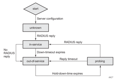
A RADIUS server is declared “out-of-service” when the down-timeout timer expires. The router starts the down-timeout timer when an access-request is sent. The timer only resets to “0” when a reply is received from the RADIUS server. This means that the timer can be reset to “0” if a reply message is received for another subscriber. For example, the RADIUS server may miss a message but stay “in-service” as long as the server responds to another access request from a different subscriber or from a retry of the same subscriber, as long as the reply is received within the down-timeout interval.
| Note: It is highly recommended that the down-timeout command be set to its default value, which is no down-timeout. |
The down-timeout default value is the timeout value multiplied by the number of retry attempts. The timeout value is the time that the router waits for the RADIUS server to reply, and the retry value is the number of attempts the 7750 SR will make to contact the RADIUS server after each timeout. If the RADIUS server remains unresponsive, the timer will continue to increment until it reaches the configured down-timeout value and the server is declared “out-of-service”.
For RADIUS servers that do not respond to all RADIUS requests, a test user account can be optionally set up to periodically send RADIUS request messages in order to keep the server in service. Typically, a RADIUS server should always respond to all access requests. However, creating a test user account for periodic keep-alive may place an unnecessary load on the processor and may lower the overall scale of the router.
At the start of the out-of-service state, a hold-down-time timer starts. The timer holds down the RADIUS server and prevents it from operating; no RADIUS messages are sent to an out-of-service server. This is beneficial for the following reasons.
- The server may be unresponsive due to excessive RADIUS message requests; holding it down allows the server to recover.
- Holding down an unresponsive server allows other healthy RADIUS servers to service new requests promptly.
After the hold-down-time timer expires, the server enters into the “probing” state. There must be multiple RADIUS servers and at least one healthy server in order for the server to enter the probing state. Probing is always performed by the test user account; actual subscriber requests are never used during probing. If no test user account exists, an actual subscriber request is used to perform the probe. There are no retry attempts; only a single RADIUS message is used to probe a RADIUS server. If the RADIUS server responds, it is declared “in-service” immediately. If the RADIUS server fails to respond within the timeout value, it is declared “out-of-service” again and the hold-down-time timer restarts. Subscriber RADIUS messages used for probing are not cached, and if the server fails to respond, the subscriber is required to send the RADIUS message again by sending an address request; for example, DHCP, PPP, or SLAAC or by performing a data-trigger.
9.3.5. AAA RADIUS Accounting Server Stickiness
Stickiness applies to the following subscriber RADIUS accounting sessions: start, interim, and stop. By default, the subscriber sticks with the server that served its last accounting message. For example, if server 1 served the subscriber an accounting start message, then the subsequent interim messages and stop message from the same subscriber will be sent to server 1. If server 1 is out of service, server 2 is used for the subsequent interim and stop messages. When server 1 recovers, the interim and stop messages will stick with server 2. The RADIUS accounting messages will always be forwarded to the server that serviced the subscriber’s last accounting message.
Typically, when using the direct access algorithm, the primary server (lowest configured server index) serves all RADIUS request messages. The other RADIUS servers are used for backup purposes only and might be using a lighter-weight processor. Therefore, it is best to revert to the primary server as soon as it is restored. This can be accomplished by disabling stickiness in direct mode; the RADIUS accounting messages will be forwarded to the primary server once it is restored.
In a round-robin algorithm, while each subscriber session is assigned to a different server in round-robin order, a particular subscriber sticks with a particular server for the entire accounting session. Disabling stickiness will send a subscriber’s RADIUS accounting messages to the list of configured RADIUS servers in a round-robin order.
9.3.6. AAA RADIUS Authentication Fallback Action
The fallback action comes into effect when connectivity to all RADIUS servers is lost. The operating state of the RADIUS servers changes to either “out-of-service” or “probing”. There are two configurable fallback actions: accept or user-db. An accept action without force-probing will automatically accept all authentication requests from all subscribers. A user-db action without force-probing will use the local-user-db for subscriber authentication.
Both accept and user-db can be combined with the force-probing command. Force-probing forces the out-of-service server to transition to the probing state immediately, bypassing the hold-down-time timer. Force-probing is a mechanism to promptly restore connectivity to a RADIUS server. A test user is not used to perform a force probe; only actual subscriber authentication will be used to test the operating state of the RADIUS server. Probing only occurs when a server is out of service. If all servers are in the probing state, all new incoming authentication requests follow the fallback action immediately.
When probing with an actual subscriber authentication, the 7750 SR will only wait for a reply for one timeout interval without any retries. During the wait, the server will be in a probing state and no other subscribers will be used to probe this server. The subscriber authentication request is not cached when used for probing. Therefore, to trigger authentication again, the subscriber is required to authenticate again with an address request or a data-trigger packet.
9.3.7. AAA Test User Account
A test user account is used in the rare case where a RADIUS server ignores RADIUS messages as mentioned in the AAA RADIUS Server Operation Status section. Consequently, when messages are ignored, the router places the RADIUS server out of service. The test user account can keep a RADIUS server in service by periodically sending RADIUS requests to the server. The RADIUS server, while randomly ignoring other subscriber RADIUS requests, must respond to the test user requests. A RADIUS server is in service if it replies to RADIUS messages before the down-timeout timer expires. The default down-timeout default value is the timeout value multiplied by the retry value, but it is also configurable. The test user account has a configurable interval value, and it is recommended that this value be configured to be less than the down-timeout value for it to be useful. The test user account only applies to RADIUS authentication.
Typically, a RADIUS server always responds to all RADIUS requests, and therefore it is not recommended that a test user account be used unless it is absolutely required for certain types of servers. The test user account creates extra load for the processor and can affect scaling. The test user account can be used with a python script (for example, adding additional attributes to the test user account during an access-request operation).
9.3.8. Troubleshooting the RADIUS Server
The tools>perform>security>authentication-server-check command can be used to troubleshoot a RADIUS server by checking the connectivity and functional status of a RADIUS server for subscriber management operations. The command keyword debug can be specified to view additional information on the access request. All VSAs sent and received from the RADIUS server, the hex dump, and all other debug detailed information can be shown without the need to turn on system-wide debugging.
Additional attributes in an Access-Request message can be specified in an attribute file referenced with the command keyword attr-from-file file-url. Each attribute must be specified on a separate line in the text file in the following format:
Table 53: authentication-server-check Attribute File Format
Attribute file format | Description |
<type> = <value> | Standard attribute |
<vendor>,<type> = <value> | Vendor Specific Attribute |
e,<type>,<ext-type> = <value> | Extended type attribute (RFC 6929) |
evs, <type>, <vendor>, <vendortype>= <value> | Extended Vendor Specific attribute(RFC 6929) |
le,<type>,<ext-type> = <value> | Long Extended type attribute (RFC6929) |
evs, <type>, <vendor>, <vendortype>= <value> | Long Extended Vendor Specific attribute(RFC 6929) |
9.3.9. Provisioning of Enhanced Subscriber Management (ESM) Objects
In the ESM concept on network elements, a subscriber host is described by the following aspects:
- subscriber-id-string
- subscriber-profile-string
- sla-profile-string
- ancp-string
- intermediate-destination-identifier-string
- application-profile-string
This information is typically extracted from DHCP-ACK message using a Python script, and is used to provision subscriber-specific resources such as queues and filter entries. As an alternative to extracting this information from DHCP-ACK packet, provisioning from RADIUS server is supported.
As a part of this feature, the following VSAs have been defined:
- alc-subscriber-id-string — Contains a string which is interpreted as a subscriber-id.
- alc-subscriber-profile-string — Contains a string which is interpreted as a subscriber profile
- alc-sla-profile-string — Contains string which is interpreted as an SLA profile.
- alc-ancp-string — Contains string which is interpreted as an ANCP string.
- alc-int-dest-id-string — Contains a string which is interpreted as an intermediate destination ID
- alc-app-profile-string — Contains a string which is interpreted as an application profileNote that these strings can be changed in a CoA request.
When RADIUS authentication response messages contain the above VSAs, the information is used during processing of DHCP-ACK message as an input for the configuration of subscriber-host parameters, such as QoS and filter entries.
If ESM is not enabled on a given SAP, information in the VSAs is ignored.
If ESM is enabled and the RADIUS response does not include all ESM-related VSAs (an ANCP string is not considered as a part of ESM attributes), only the subscriber-id is mandatory (the other ESM-related VSAs are not included). The remaining ESM information (sub-profile, sla-profile) will be extracted from DHCP-ACK message according to “normal” flow (Python script, and so on).
If the profiles are missing from RADIUS, they are not extracted from the DHCP data with Python to prevent inconsistent information. Instead, he data will revert to the configured default values.
However, if the above case, a missing subscriber ID will cause the DHCP request to be dropped. The DHCP server will not be queried in that case.
When no DHCP server is configured, DHCP-discover/request messages are discarded.
9.3.9.1. Provisioning IP Configuration of the Host
The other aspect of subscriber-host authorization is providing IP configuration (ip-address, subnet-mask, default gateway and dns) through RADIUS directory rather then using centralized DHCP server. In this case, the node receiving following RADIUS attributes will assume role of DHCP server in conversation with the client and provide the IP configuration received from RADIUS server.
These attributes will be accepted only if the system is explicitly configured to perform DHCP-server functionality on a given interface.
The following RADIUS attributes will be accepted from authentication-response messages:
- framed-ip-address — The IP address to be configured for the subscriber-host.
- framed-ip-netmask — The IP network to be configured for the subscriber host. If RADIUS does not return a netmask, the DHCP request is dropped.
- framed-pool — The pool on a local DHCP server from which a DHCP-provided IP address should be selected.
- alc-default-router — The address of the default gateway to be configured on the DHCP client.
- alc-primary-dns — The DNS address to be provided in DHCP configuration.
- Juniper VSA for primary DNS.
- Redback VSA for primary DNS.
- alc-secondary-dns
- Juniper VSA for secondary DNS.
- Redback VSA for secondary DNS.
- alc-lease-time — Defines the lease time.
- session-timeout — Defines the lease time in absence of the alc-lease-time attribute.
- NetBIOS
- alc-primary-nbns
- alc-secondary-nbns
9.3.9.2. RADIUS Based Authentication in Wholesale Environment
In order to support VRF selection, the following attributes are supported:
- alc-retail-serv-id — Indicates the service-id of the required retail VPRN service configured on the system.
9.3.9.3. Change of Authorization and Disconnect-Request
In a typical RADIUS environment, the network element serves as a RADIUS client, which means the messages are originated by a routers. In some cases, such as “mid-session” changes, it is desirable that the RADIUS server initiates a CoA request to impose a change in policies applicable to the subscriber, as defined by RFC 3576.
To configure a RADIUS server to accept CoA and Disconnect Messages is achieved in one of the following ways:
- Configure up to 64 RADIUS CoA servers per routing instance: config>router>radius-server# config>service>vprn>radius-server# server "coa-1" address 10.1.1.1 secret <shared-secret> hash2 createaccept-coa exitThis is the preferred method.
- Configure up to 16 RADIUS CoA servers per authentication policy. config>subscr-mgmt>auth-plcy# accept-authorization-changeThe UDP port for CoA and Disconnect Messages is configurable per system with the command: config>aaa# radius-coa-port {1647|1700|1812|3799}
| Note: There is a priority in the functions that can be performed by CoA. The first matching one will be performed:
|
There are several reasons for using RADIUS initiated CoA messages:
- Changing ESM attributes (SLA or subscriber profiles) or queues/policers/schedulers rates of the given subscriber host — CoA messages containing the identification of the given subscriber-host along with new ESM attributes.
- Changing (or triggering the change) of IP configuration of the given subscriber-host — CoA messages containing the identification of the given subscriber-host along with VSA indicating request of forcerenew generation.
- Configuring new subscriber-host — CoA messages containing the full configuration for the given host.
If the changes to ESM attributes are required, the RADIUS sever will send CoA messages to the network element requesting the change in attributes included in the CoA request:
- attribute(s) to identify a single or multiple subscriber host(s): “NAS-Port-Id + IP address/prefix” or “Acct-Session-Id” or “Alc-Subsc-ID-Str”
- Nas-Port-Id attribute + single IP address/prefix attribute:
- Framed-IP-Address
- Alc-Ipv6-Address
- Framed-Ipv6-Prefix
- Delegated-Ipv6-Prefix
- Acct-Session-Id (number format)
- Alc-Subsc-ID-Str
- alc-subscriber-profile-string
- alc-sla-profile-string
- alc-ancp-string
- alc-app-profile-string
- alc-int-dest-id-string
- alc-subscriber-id-string
- alc-subscriber-qos-override

Note: If the subscriber-id-string is changed while the ANCP string is explicitly set, the ANCP-string must be changed simultaneously. When changing the alc-subscriber-id-string, the lease state is temporarily duplicated, causing two identical ANCP-strings to be in the system at the same time. This is not allowed.
As a reaction to such message, the router changes the ESM settings applicable to the given host.
If changes to the IP configuration (including the VRF-id in the case of wholesaling) of the given host are needed, the RADIUS server may send a CoA message containing VSA indicating request for forcerenew generation:
- attribute(s) to identify a single or multiple subscriber host(s): “NAS-Port-Id + IP address/prefix” or “Acct-Session-Id” or “Alc-Subsc-ID-Str”:
- Nas-Port-Id attribute + single IP address/prefix attribute:
- Framed-IP-Address
- Alc-Ipv6-Address
- Framed-Ipv6-Prefix
- Delegated-Ipv6-Prefix
- Acct-Session-Id (number format)
- Alc-Subsc-ID-Str
- alc-force-renew
- alc-force-nak
As a reaction to such message, router will generate a DHCP forcerenew message for the given subscriber host. Consequently, during the re-authentication, new configuration parameters can be populated based on attributes included in Authentication-response message. The force-NAK attribute has the same function as the force-renew attribute, but will cause the ESR to reply with a NAK to the next DHCP renew. This will invalidate the lease state on the ESR and force the client to completely recreate its lease, making it possible to update parameters that cannot be updated through normal CoA messages, such as IP address or address pool.
If the configuration of the new subscriber-host is required, RADIUS server will send a CoA message containing VSA request new host generation along with VSAs specifying all required parameters.
- alc-create-host
- alc-subscriber-id-string — This attribute is mandatory in case ESM is enabled, and optional for new subscriber host creation otherwise.
- NAS-port-id — This attribute indicates the SAP where the host should be created.
- framed-ip-address — The framed IP address.
- alc-client-hw-address — A string in the xx:xx:xx:xx:xx:xx format. This attribute is mandatory for new subscriber-host creation.
- alc-lease-time — Specifies the lease time. If both session-timeout and alc-lease-time are not present, then a default lease time of 7 days is used.
- session-timeout — Specifies the lease time in absence of the alc-lease-time attribute. If both session-timeout and alc-lease-time are not present, then a default lease time of 7 days is used.
- alc-retail-svc-id — This is only used in case of wholesaling for selection of the retail service. Indicates the service-id of the required retail VPRN service configured on the system.
- Optionally other VSAs describing given subscriber host. Obviously, if the ESM is enabled, but the CoA message does not contain ESM attributes the new host will not be created.
After executing the requested action, the router element responds with an ACK or NAK message depending on the success/failure of the operation. In case of failure (and hence NAK response), the element will include the error code in accordance with RFC 3576 definitions if an appropriate error code is available.
Supporting CoA messages has security risks as it essentially requires action to unsolicited messages from the RADIUS server. This can be primarily the case in an environment where RADIUS servers from multiple ISPs share the same aggregation network. To minimize the security risks, the following rules apply:
- Support of CoA messages is disabled by default. They can be enabled on a per RADIUS server or authentication-policy basis.
- When CoA is enabled, the node will listen and react only to CoA messages received from RADIUS servers. In addition, CoA messages must be protected with the key corresponding to the given RADIUS server. All other CoA messages will be silently discarded.
In all cases (creation, modification, forcerenew) subscriber host identification attributes are mandatory in the CoA request: “NAS-Port-Id + IP” or “Acct-Session-Id” or “Alc-Subsc-ID-Str”
- Nas-Port-Id + single IP address/prefix:
- Nas-Port-Id
- Framed-IP-Address
- Alc-Ipv6-Address
- Framed-Ipv6-Prefix
- Delegated-Ipv6-Prefix
- Acct-Session-Id (number format)
- Alc-Subsc-ID-Str
When there are no subscriber host identification attributes present in the CoA, the message will be NAK’d with corresponding error code.
- hosts, meaning only subscriber host to which the given authentication-policy is applicable.
- Receiving CoA message with the same attributes as currently applicable to the given host will be responded to with an ACK message.
- In case of dual homing (through SRRP), the RADIUS server should send CoA messages to both redundant nodes and this with all corresponding attributes (NAS-port-id with its local meaning to corresponding node).
- In the case of change requests, the node which has the given host active (active-sap for master-sap for SRRP) will process the RADIUS message and reply to RADIUS. The standby node will always reply with a NAK.
- In the case of create requests, the active node (the SAP described by NAS-port-id is “active” or “master”). Both nodes will reply, but the standby will NAK the request.
The properties of an existing RADIUS-authenticated PPPoE session can be changed by sending a Change of Authorization (CoA) message from the RADIUS server. Processing of a CoA is done in the same way as for DHCP hosts, with the exception that only the ESM settings can be changed for a PPPoE session (the force-renew attribute is not supported for PPPoE sessions and a Create-Host CoA will always generate a DHCP host.)
For terminating PPPoE sessions from the RADIUS server, the disconnect-request message can be sent from the RADIUS server. This message triggers a shutdown of the PPPoE session. The attributes needed to identify the PPPoE session are the same as for DHCP hosts.
9.3.9.4. RADIUS-Based Accounting
When a router is configured to perform RADIUS-based accounting, at the creation of a subscriber-host, it will generate an accounting-start packet describing the subscriber-host and send it to the RADIUS accounting server. At the termination of the session, it will generate an accounting-stop packet including accounting statistics for a given host. The router can also be configured to send an interim-accounting message to provide updates for a subscriber-host.
The exact format of accounting messages, their types, and communication between client running on the routers and RADIUS accounting server is described in RFC 2866, RADIUS Accounting. The following describes a few specific configurations.
In order to identify a subscriber-host in accounting messages different RADIUS attributes can be included in the accounting-start, interim-accounting, and accounting-stop messages. The inclusion of the individual attributes is controlled by the following commands.
RADIUS volume accounting attributes are depending on the type of volume reporting and can be controlled via an include-radius-attribute CLI command. Multiple volume reporting types can be enabled simultaneously:
where:
detailed-acct-attributes — Report detailed per queue and per policer counters using RADIUS VSAs (enabled by default). Each VSA contains a queue or policer id followed by the stat-mode or 64 bit counter. The VSA’s included in the Accounting messages is function of the context (policer or queue, stat-mode, MDA type, an so on):
[26-6527-107] Alc-Acct-I-statmode
[26-6527-127] Alc-Acct-O-statmode
[26-6527-19] Alc-Acct-I-Inprof-Octets-64
[26-6527-20] Alc-Acct-I-Outprof-Octets-64
[26-6527-21] Alc-Acct-O-Inprof-Octets-64
[26-6527-22] Alc-Acct-O-Outprof-Octets-64
[26-6527-23] Alc-Acct-I-Inprof-Pkts-64
[26-6527-24] Alc-Acct-I-Outprof-Pkts-64
[26-6527-25] Alc-Acct-O-Inprof-Pkts-64
[26-6527-26] Alc-Acct-O-Outprof-Pkts-64
[26-6527-39] Alc-Acct-OC-O-Inprof-Octets-64
[26-6527-40] Alc-Acct-OC-O-Outprof-Octets-64
[26-6527-43] Alc-Acct-OC-O-Inprof-Pkts-64
[26-6527-44] Alc-Acct-OC-O-Outprof-Pkts-64
[26-6527-69] Alc-Acct-I-High-Octets-Drop_64
[26-6527-70] Alc-Acct-I-Low-Octets-Drop_64
[26-6527-71] Alc-Acct-I-High-Pack-Drop_64
[26-6527-72] Alc-Acct-I-Low-Pack-Drop_64
[26-6527-73] Alc-Acct-I-High-Octets-Offer_64
[26-6527-74] Alc-Acct-I-Low-Octets-Offer_64
[26-6527-75] Alc-Acct-I-High-Pack-Offer_64
[26-6527-76] Alc-Acct-I-Low-Pack-Offer_64
[26-6527-77] Alc-Acct-I-Unc-Octets-Offer_64
[26-6527-78] Alc-Acct-I-Unc-Pack-Offer_64
[26-6527-81] Alc-Acct-O-Inprof-Pack-Drop_64
[26-6527-82] Alc-Acct-O-Outprof-Pack-Drop_64
[26-6527-83] Alc-Acct-O-Inprof-Octs-Drop_64
[26-6527-84] Alc-Acct-O-Outprof-Octs-Drop_64
[26-6527-91] Alc-Acct-OC-O-Inpr-Pack-Drop_64
[26-6527-92] Alc-Acct-OC-O-Outpr-Pack-Drop_64
[26-6527-93] Alc-Acct-OC-O-Inpr-Octs-Drop_64
[26-6527-94] Alc-Acct-OC-O-Outpr-Octs-Drop_64
[26-6527-108] Alc-Acct-I-Hiprio-Octets_64
[26-6527-109] Alc-Acct-I-Lowprio-Octets_64
[26-6527-110] Alc-Acct-O-Hiprio-Octets_64
[26-6527-111] Alc-Acct-O-Lowprio-Octets_64
[26-6527-112] Alc-Acct-I-Hiprio-Packets_64
[26-6527-113] Alc-Acct-I-Lowprio-Packets_64
[26-6527-114] Alc-Acct-O-Hiprio-Packets_64
[26-6527-115] Alc-Acct-O-Lowprio-Packets_64
[26-6527-116] Alc-Acct-I-All-Octets_64
[26-6527-117] Alc-Acct-O-All-Octets_64
[26-6527-118] Alc-Acct-I-All-Packets_64
[26-6527-119] Alc-Acct-O-All-Packets_64
std-acct-attributes — Report IPv4 and IPv6 aggregated forwarded counters using standard RADIUS attributes (disabled by default):
[42] Acct-Input-Octets
[43] Acct-Output-Octets
[47] Acct-Input-Packets
[48] Acct-Output-Packets
[52] Acct-Input-Gigawords
[53] Acct-Output- Gigawords
v6-aggregate-stats — Report IPv6 aggregated forwarded counters of queues and policers in stat-mode v4-v6 using RADIUS VSAs (disabled by default):
[26-6527-194] Alc-IPv6-Acct-Input-Packets
[26-6527-195] Alc-IPv6-Acct-Input-Octets
[26-6527-196] Alc-IPv6-Acct-Input-GigaWords
[26-6527-197] Alc-IPv6-Acct-Output-Packets
[26-6527-198] Alc-IPv6-Acct-Output-Octets
[26-6527-199] Alc-IPv6-Acct-Output-Gigawords
In addition to accounting-start, interim-accounting, and accounting-stop messages, a RADIUS client on a routers will send also accounting-on and accounting-off messages. An accounting-on message will be sent when a given RADIUS accounting-policy is applied to a given subscriber-profile, or the first server is defined in the context of an already applied policy. The following attributes will be included in such message:
- NAS-identifier
- alc-subscriber-profile-string
- Accounting-session-id
- Event-timestamp
Accounting-off messages will be sent at following events:
- An accounting policy has been removed from a sub-profile.
- The last RADIUS accounting server has been removed from an already applied accounting policy.
These messages contain following attributes:
- NAS-identifier
- alc-subscriber-profile-string
- Accounting-session-id
- Accounting-terminate-cause
- Event-timestamp
In case of dual homing, both nodes will send RADIUS accounting messages for the host, with all attributes as it is locally configured. The RADIUS log files on both boxes need to be parsed to get aggregate accounting data for the given subscriber host regardless the node used for forwarding.
For RADIUS-based accounting, a custom record can be defined to refine the data that is sent to the RADIUS server. Refer to the Configuring an Accounting Custom Record in the OS System Management Guide for further information.
9.3.9.5. RADIUS Accounting Terminating Cause
The VSA acct-terminate-cause attribute provides some termination information. Two additional attributes: [VSA 227] alc-error-message and [VSA 226] alc-error-code provide additional information in both string and numeric format about the terminating cause of the subscriber session. The full list of error messages and their corresponding error codes can be viewed using the command tools>dump>aaa> radius-acct-terminate-cause.
If required, python can alter the content of both VSAs. The following is a python script example where the error codes are remapped from 123 to 8 and from 124 to 17:
9.3.9.6. Accounting Modes Of Operation
This section is applicable to the 7750 SR or the 7450 ESS in mixed mode. There are three basic accounting models:
- Per queue-instance
- Per Host
- Per Session
Each of the basic models can optionally be enabled to send interim-updates. Inclusion/exclusion of interim-updates will depend on whether volume based (start/interim-updates/stop) or time based (start/stop) accounting is required.
The difference between the three basic accounting models is in its core related to the processing of the acc-session-id for each model. The differences are related to:
- acct-session-id generation within each model.
- outcome in response to the CoA action relative to the targeted acct-session-id.
The counters for volume-based accounting are collected from queues or policers that are instantiated per sla-profile instance (SPI) on non-HSMDA based hardware or per subscriber on HSMDA based hardware. This is true irrespective of which model of accounting (or combination of models) is deployed. Within accounting context, the SPI on non-HSMDA or subscriber on HSMDA equates to queue-instance.
Table 54 summarizes the key differences between various accounting modes of operation that are supported. Interim-updates for each individual mode can be enabled/disabled via configuration (interim-updates keyword as an extension to the commands that enable three basic modes of accounting). This is denoted by the IU-Config keyword under the ‘I-U’ column in the table. The table also shows that any two combinations of the three basic models (including their variants for volume/time based accounting) can be enabled simultaneously.
Table 54: Accounting Modes of Operation
Accounting Mode | Accounting Entity | START | I-U | STOP | Acct-session-id | Acct-multi- session-id |
queue-instance-accounting | queue-instance | X | IU-config | X | X | |
session | ||||||
host | ||||||
session-accounting | queue-instance | |||||
session | X | IU-config | X | X | q-instance | |
host | ||||||
host-accounting | queue-instance | |||||
session | ||||||
host | X | IU-config | X | X | queue-instance | |
queue-instance-accounting + host-accounting | queue-instance | X | IU-config | X | X | queue-instance |
session | ||||||
host | X | IU-config | X | X | queue-instance | |
queue-instance-accounting + session-accounting | queue-instance | X | IU-config | X | X | queue-instance |
session | X | IU-config | X | X | queue-instance | |
host | ||||||
session- accounting + host-accounting | queue-instance | queue-instance | ||||
session | X | IU-config | X | X | ||
host | X | X | X | SESSION |
| Note: Hosts within the targeted CoA entity will be affected as follows:
|
The same principle applies to LI.
The accounting behavior (accounting messages and accounting attributes) in case that the SPI is changed via CoA depends on the accounting mode of operation. On non-HSMDA hardware, the behavior is the following:
- SPI change in conjunction with per queuing instance accounting will trigger a STOP for the old SPI and a START for the new SPI with corresponding counters. Acct-session-id/Acct-Multi-Session-Id will be unique per SPI. Note that Acct-Multi-Session-Id is only generated if per queuing-instance accounting mode of operation is combined with some other mode of operation (host or session).
- SPI change in conjunction with per host or per session accounting (no interim updates for either method) will NOT trigger any new accounting messages. In other words, SPI change will go unnoticed from the perspective of the accounting server until the host/session is terminated. When the host/session is terminated a STOP will be sent with the VSA carrying the latest SPI name and the acct-multi-session-id attribute of the latest SPI. Acct-session-id will stay the same during the lifetime of the host. Counters are not included in STOP (interim-update not enabled).SPI change in conjunction with per host accounting with interim-updates or per session accounting with interim-updates will trigger two interim-update messages:
- One with the old counters (terminated queues) and the old SPI name VSA. This behavior is similar to the triggered STOP message in per queuing-instance accounting upon SPI change.
- One with the new counters (new queues instantiated), the VSA carrying the new SPI name and the new acct-multi-session-id referencing the new SPI. This behavior is similar to the triggered START message in per queuing-instance when SPI is changed in per queuing-instance accounting.
On HSMDA, no START/STOPS are sent since queues are not re-instantiated on ingress or egress.
9.3.9.7. Per Session Accounting
In the per session accounting mode of operation the accounting message stream (START/INTERIM-UPDATE/STOP) is generated per session. The accounting message stream refers to a collection of accounting messages (START/INTERIM-UPDATE/STOP) sharing the same acct-session-id.
- A session is defined for PPPoE hosts for which a state is maintained. The state of the host (single stack or dual-stack) is normally refreshed via PPP keepalives. Each PPPoE host of the same address family (v4 or v6) corresponds to a unique session which is identified by the <session-ID, mac> combination.
In dual-stack PPPoE case, IPv4 and IPv6 hosts are tied to the same (LCP) session. A single authentication request is initiated for such session (triggered by the first host that initiates the session).
For a single stack PPPoE host, the behavior defined in the per session accounting model is indistinguishable from the per host accounting model. The per session accounting model makes difference in behavior only for dual stack PPPoE hosts.
The following are the properties of the Per Session Accounting model:
- A single accounting session ID (acct-session-id) is generated per (PPPoE) session and it can optionally be sent in RADIUS Access-Request message.
- This acct-session-id is synchronized via MCS in dual homing environment.
- The accounting messages (START, INTERIM-UPDATE, STOP) carry the acct-multi-session-id attribute denoting the sla-profile instance with which the session is associated.
- The counters are collected from the queues instantiated through the sla-profile instance. If multiple sessions are sharing the same sla-profile instance, the counters are aggregated. In other words, counters per individual session cannot be extracted from the aggregated count.
- RADIUS triggered changes and LI are applicable per session:
- Queue/policer RADIUS overrides — Parameters for the referenced queue/policer within the session are changed accordingly.
- Subscriber aggregate rate limits, scheduler rates and arbiter rates are changed accordingly.
- CoA DISCONNECT brings down the entire session.
- LI — Activation based on the session acct-session-id affects the hosts within the session (dual-stack).
- SLA profile instance change affects all hosts (or sessions) sharing the same sla-profile instance (SPI). If the SPI is changed on a non-HSMDA based MDA, then queues are re-instantiated and counters are reset.
- All applicable IP addresses (v4 and v6 – including all v6 attributes – alc-ipv6-address, framed-ipv6-prefix, delegated-ipv6-prefix) are present in accounting messages for the session.
9.3.9.7.1. Caveats
Per session accounting is supported for entities that have concept of a session. Currently only PPPoE hosts (single or dual-stack) fall into this category.
9.3.9.8. RADIUS Session Accounting with PD as a Managed Route
The Prefix Delegation (PD) prefix is included in the accounting messages using the VSA [99], Framed-IPv6-Route attribute with the string type “pd-host” appended to differentiate it from a regular framed IPv6 route; for example, FRAMED IPV6 ROUTE [99] 39 2001:1000::/64 :: 0 pref 0 type pd-host. PD as a managed route is applicable to both PPP and IPoE sessions and can point either to an IPv4 host or to an IPv6 WAN host.
Table 55 outlines the RADIUS accounting behavior based on the session type and the next-hop host.
Table 55: Radius Accounting Behavior
Session Type and Next-Hop Host | RADIUS Accounting Start | RADIUS Accounting Interims | RADIUS Accounting Stop |
PPP session with IPv6 PD pointing to IPv4 host as the next hop | A PPP connection will trigger an accounting start | A DHCP NA+PD solicit will trigger an interim update for the PD host with interim reason “delegated-ipv6-prefix-up” and the prefix included in the VSA Framed-IPv6-Route A DHCP PD solicit will trigger an interim update for the PD host with interim reason delegated-ipv6-prefix-up and the prefix included in the VSA framed-ipv6-route Caveat
| A PPP disconnect with only the IPv4 and IPv6 PD host will trigger an accounting stop with the prefix included in the VSA Framed-IPv6-Route Caveat
|
PPP session with IPv6 PD pointing to IPv6 NA host as the next hop | A PPP connection will trigger an accounting start. It is possible to have a single-stack IPv6-only session | A DHCP NA+PD solicit will trigger an interim update for the PD host with interim reason delegated-ipv6-prefix-up and the prefix included in the VSA framed-ipv6-route Caveat
| A PPP subscriber disconnect will trigger an accounting stop with the PD host prefix included in the VSA Framed-IPv6-Route |
IPoE session with IPv6 PD pointing to IPv4 host as the next hop | A DHCPv4 or a DHCPv6 request (DHCPv6 always performs NA and PD requests together) will trigger the accounting start | A DHCP PD is always performed together with NA. The PD is not in the start message but is included in the accounting interim update as a part of the host update. If the DHCPv4 lease expires, the interim update will contain the PD prefix in the VSA framed-ipv6-route Caveat
| If only the IPv4 host and PD host remain, the release of the DHCPv4 will trigger an accounting stop with the PD host prefix included in the VSA Framed-IPv6-Route Caveat
|
IPoE session with IPv6 PD pointing to IPv6 NA host as the next hop | A DHCPv4 or a DHCPv6 request (DHCPv6 always performs NA and PD requests together) will trigger the accounting start. It is possible to have a single-stack IPv6-only session | A DHCP PD is always performed together with NA. The PD is not in the start message but is included in the accounting interim update as a part of the host update. Caveat
| If only the IPv6 subscriber is left, the release of NA will contain the prefix of the PD host Caveat
|
RADIUS Per Host Accounting
In SR-OS, the accounting paradigm is based on SLA profile instances yet this is at odds with traditional RADIUS authentication and accounting which is host-centric. In previous SR-OS releases, it was possible to have many hosts sharing a common SLA profile instance, and thus accounting and QoS parameters. Complications would arise with RADIUS accounting because Accounting-Start and Accounting-Stop are a function of sla-profile instance and not the hosts — this meant that some host-specific parameters (like framed-ip-address) would not be consistently included in RADIUS accounting.
Currently, dual-stack subscribers are really two different hosts sharing a single sla-profile instance. A new RADIUS accounting mode has been introduced to support multiple-host environments.
Under accounting-policy, a host-accounting command allows configurable behavior.
9.3.9.9. No Host-Accounting
In prior releases and when no host-accounting is configured, the accounting behavior is as follows:
- A RADIUS accounting start message is sent when the SLA-profile instance is created. It contains accounting (octets/packets) and the framed-ip-address of the host which caused the sla-profile instance to be created.
- Additional hosts may bind to the sla-profile instance at any time, but no additional Accounting messages are sent during these events.
- If the original host disconnects then future Accounting messages will use an IP address of one of the remaining hosts.
- When the final host associated with an sla-profile instance disconnects an Accounting Stop message will be sent.
9.3.9.10. Host-Accounting Enabled
When host-accounting is configured, additional RADIUS accounting messages are created for host activity in addition to messages for common queue accounting. The behavior is as follows:
- A RADIUS accounting start message is sent each time a host is authenticated. It contains the framed-ip-address among other things. It does not contain any octet or packet counts.
- A RADIUS accounting start message is sent each time a sla-profile instance is created.
- Whenever a host disconnects a RADIUS accounting stop message is sent for that host.
- If all host associated with an sla-profile instance disconnect, a RADIUS Accounting Stop message is sent for that instance.
This new behavior means certain AVP may be in either host; sla-profile instance or both accounting records.
Note that interim-acct records are not sent for hosts, only the start- and stop-accting messages.
Table 56:
RADIUS Accounting AVP | Include-radius-attrs Acct/Auth | Host Accounting | SLA-Profile Accounting |
User-Name | Yes/No | Yes | No |
NAS-Identifier | Yes/No | Yes | Yes |
NAS-Ip-Address | No/No | Yes | Yes |
NAS-Port-Id | Yes/Yes | Yes | No |
Nas-Port | Yes/No | Yes | No |
NAS-Port-Type | Yes/Yes | Yes | No |
Service-Type | No/No | Yes | No |
Framed-Protocol | No/No | Yes | No |
Framed-Ip-Address | Yes/No | Yes | No |
Framed-Ip-Netmask | Yes/No | Yes | No |
Class | No/No | Yes | No |
Circuit-Id VSA | Yes/Yes | Yes | No |
Called-Station-Id | Yes/Yes | Yes | No |
Calling-Station-Id | Yes/Yes | Yes | No |
MAC-Addr VSA | Yes/Yes | Yes | No |
Remote-Id VSA | Yes/Yes | Yes | No |
Acct-Input-Octets | No/No | No | Yes |
Acct-Output-Octets | No/No | No | Yes |
Acct-Input-Gigawords | No/No | No | Yes |
Acct-Output-Gigawords | No/No | No | Yes |
Acct-Session-Id | No/No | Yes | Yes |
Acct-Session-Time | No/No | Yes | Yes |
Acct-Input-Packets | No/No | No | Yes |
Acct-Output-Packets | No/No | No | Yes |
Acct-Multi-Session-Id | No/No | Yes | Yes |
Access-Loop-Encapsulation | No/Yes | Yes | No |
Alc-Subscriber-Id | Yes/No | Yes | Yes |
Alc-Subscriber-Profile-String | Yes/No | Yes | Yes |
Alc-Sla-Profile-String | Yes/No | Yes | Yes |
9.3.9.11. Reduction of Host Updates for Session Accounting Start and Stop
When host-update is enabled In session accounting, a dual stack subscriber can generate multiple host update accounting messages at the start and end of a session (for example, one for the IPv4 host and two more for the IPv6 WAN and IPv6 PD hosts). Two features can be used to reduce the number of host update messages per subscriber.
The first feature delays the Start Accounting message by a configurable value and is applicable to both PPPoE and IPoE sessions. The command for configuring this feature is config>subscr-mgmt>acct-plcy>delay-start-time. The delay allows the full dual stack address assignment to be completed before triggering the accounting Start message. The Start message reports all the addresses and prefixes assigned to the subscriber at that time. Subsequent new or disconnected hosts will trigger interim host updates if enabled.
The second feature is for PPPoE sessions only and is used to reduce the number of host update messages when a dual stack PPP subscriber disconnects. The command for configuring this feature is config>subscr-mgmt>sub-prof>rad-acct>session-optimized-stop. A single accounting Stop message containing all the addresses and prefixes for the subscriber at the time is generated.
9.3.9.12. Accounting Interim Update Message Interval
The interval between two RADIUS Accounting Interim Update messages can be configured in the RADIUS accounting policy with the update-interval command, for example:
A RADIUS specified interim interval (attribute [85] Acct-Interim-Interval) overrides the CLI configured value.
By default, a random delay of 10% of the configured update-interval is added to the update-interval between two Accounting Interim Update messages. This jitter value can be configured with the update-interval-jitter to an absolute value in seconds between zero and 3600. The effective maximum random delay value is the minimum value of the configured absolute jitter value and 10% of the configured update-interval.
A value of zero will send the Accounting Interim Update message without introducing an additional random delay.
9.3.9.13. CoA Triggered Accounting Interim Update
The vendor-specific attribute (VSA) [228], Alc-Triggered-Acct-Interim, can be used in a Change of Authorization message to trigger an interim accounting message. This feature requires the accounting mode to have interim updates enabled. You can enable interim updates using, the config>subscr-mgmt>radius-acct-plcy>host-accounting interim-update command. The VSA can hold a string of up to 247 characters. The accounting interim echoes this string in the interim message under the same Alc-Triggered-Acct-Interim VSA along with Alc-Acct-Triggered-Reason = CoA-triggered. If the VSA is left blank, it will still trigger the accounting interim message with Alc-Acct-Triggered-Reason = CoA-triggered (18), but without the Alc-Triggered-Acct-Interim attribute. If the subscriber session has multiple accounting policies or modes enabled, multiple interim messages will be generated.Some CoAs, such as SLA profile or sub-profile changes, will trigger accounting update messages to be generated automatically. These CoAs can automatically generate one or more accounting interim messages. If these CoAs also include the Alc-Triggered-Acct-Interim VSA, no additional interim accounting messages will be generated. The last auto-generated accounting interim message will contain two reasons:
- the reason for the triggered interim message (such as an SLA start)
- the CoA-triggered (18) Alc-Triggered-Acct-Interim attribute that will be echoed on the triggered accounting interim message if the VSA is not empty
9.3.9.14. Class Attribute
The RADIUS class attribute helps to aid in user identification.
User identification is used to correlate RADIUS accounting messages with the given user. During the authentication process, the RADIUS authentication server inserts a class attribute into the RADIUS authenticate response message and the router echoes this class attribute in all RADIUS accounting messages.
The 7750 SR can store up to six class attributes for both RADIUS and NASREQ. Each class VSA or AVP can have a maximum of 253 characters. If the VSA or AVP contains more than 253 characters, only the first 253 characters will be stored. If there are more than six VSAs or AVPs, only the first six will be stored. This functionality is also applicable to RADIUS authentication via the ISA.
9.3.9.15. User Name
The user-name, which is used for user authentication (user-name attribute in RADIUS authentication request), can be included in RADIUS accounting messages. Per RFC 2865, when a RADIUS server returns a (different) user-name attribute, the changed user name will be used in accounting and not the originally sent user name.
9.3.9.16. Accounting-On and Accounting Off
For RADIUS servers configured in a RADIUS server policy, the accounting on/off behavior is controlled via the acct-on-off command in the radius-server-policy.
By default, no Accounting-On or Accounting-Off messages are sent (no acct-on-off).
With the acct-on-off command configured in the radius-server-policy:
- An Accounting-On is sent for the following:
- When the system is powered on.
- After a system reboots.
- When the acct-on-off command is added to the radius-server-policy configuration.
- User triggered via CLI: tools perform aaa acct-on
- An Accounting-Off is sent for the following:
- Before a user initiated system reboot.
- When the acct-on-off command is removed from the radius-server-policy configuration.
- User triggered via CLI: tools perform aaa acct-off.
The Accounting-On or Accounting-Off message is sent to the servers configured in the radius-server-policy, following the configured access-algorithm until an Accounting Response is received. If the first server responds, no message is sent to the other servers.
The Accounting-On message is repeated until an Accounting Response message is received from a RADIUS server: If after the configured retry/timeout timers for each RADIUS server in the radius-server-policy no response is received then the process starts again after a fixed one minute wait interval.
The Accounting-Off message is attempted once: If after the configured retry/timeout timers for each RADIUS server in the radius-server-policy no response is received then no new attempt is made.
It is possible to block a radius-server-policy until an Accounting Response is received from one of the RADIUS servers in the radius-server-policy that acknowledges the reception of an Accounting-On. The radius-server-policy cannot be used by applications for sending RADIUS messages until the state becomes “Not Blocked”. This is achieved with the optional “oper-state-change” flag, for example:
If multiple radius-server-policies are in use for different applications (for example, authentication and accounting) and an Accounting-On must be send for only one radius-server-policy, it is possible to tie the acct-on-off states of both policies together using an acct-on-off-group. With this configuration, it is possible to block the authentication servers until the accounting servers are available. An acct-on-off-group can be referenced by:
- a single radius-server-policy as controller: the acct-on-off oper-state of the acct-on-off-group is set to the acct-on-off oper-state of the radius-server-policy (acts as master)
- multiple radius-server-policies as monitor: the acct-on-off oper-state of the radius-server-policy is inherited from the acct-on-off oper-state of the acct-on-off group. (acts as a slave)
It is possible to force an Accounting-On or Accounting-Off message for a radius-server-policy with acct-on-off enabled using following CLI commands:
tools perform aaa acct-on [radius-server-policy policy-name] [force]
tools perform aaa acct-off [radius-server-policy policy-name] [force] [acct-terminate-cause number]
If an Accounting-On was sent to the radius-server-policy and it was acknowledged with an Accounting Response then a new Accounting-On can only be sent with the “force” flag.
If an Accounting-Off was sent to the radius-server-policy and it was acknowledged with an Accounting Response then a new Accounting-Off can only be sent with the “force” flag. The Acct-Terminate-Cause value in the Accounting-Off can be overwritten.
Use the following CLI command to display the Accounting On/Off information for a radius-server-policy:
The operational state provides following state information: The sending of the Accounting-On or Accounting-Off message is ongoing (sendAcctOn, SendAcctOff), is successfully responded (on, off) or no response received (OffNoResp).
The Session-Id is a unique identifier for each RADIUS server policy accounting Accounting-On/Accounting-Off sequence.
The Trigger field shows what triggered the Accounting On or Accounting Off message. If the radius-server-policy is part of an acct-on-off group then the group name is shown in brackets.
The Server field shows which server in the RADIUS server policy responded to the Accounting-On or Accounting-Off message.
To display the acct-on-off state of a radius-server-policy, use the command, for example:
The Acct-On-Off field indicates if the sending of Accounting-On and Accounting-Off messages is enabled or disabled. If enabled, the oper-state is displayed: state Blocked or state Not Blocked. When Blocked, the radius-server-policy cannot be used to send RADIUS messages.
To display acct-on-off-group information, use following command, for example:
9.3.9.17. RADIUS Accounting Message Buffering
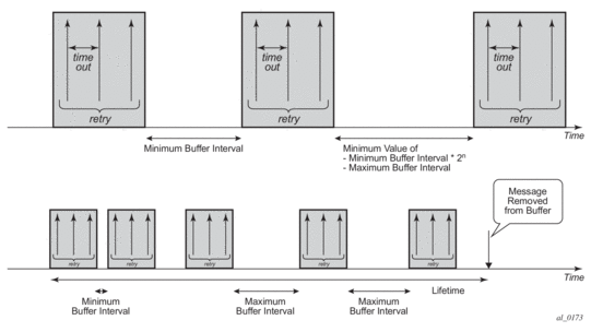
When all servers in a radius-server-policy are unreachable, it is possible to buffer the Accounting Stop and Accounting Interim-Update messages for up to 25 hours. When a RADIUS server becomes reachable again then the messages in the buffer are retransmitted.
RADIUS Accounting message buffering parameters can be configured per message type, for example:
When RADIUS accounting message buffering is enabled:
- The message is stored in the buffer, a lifetime timer is started and the message is sent to the RADIUS server.
- If after retry*timeout seconds no RADIUS accounting response is received for the Accounting Interim Update or Accounting Stop then a new attempt to send the message is started after minimum [(min-val*2n), max-val] seconds.
- Repeat step 2 until:
- RADIUS accounting response is received, or
- the lifetime of the buffered message expires, or
- (if the buffered message is an Accounting Interim-Update only) A new Accounting Interim-Update or an Accounting Stop or for the same accounting session-id and radius-server-policy is stored in the buffer, or
- the message is manually purged from the message buffer via a clear command
- The message is purged from the buffer as shown in Figure 67.
Figure 67: Purging Message from Buffer
When Accounting Interim-Update message buffering is enabled, it is recommended to also enable Accounting Stop message buffering. This will guarantee the message ordering per accounting session.
Use following clear command to manually delete messages from the RADIUS accounting message buffer:
# clear aaa radius-server-policy policy-name msg-buffer [acct-session-id acct-session-id]
When specifying the Acct-Session-Id, only that specific message will be deleted from the message buffer. If no Acct-Session-Id is specified, all messages for that radius-server-policy are deleted from the message buffer.
Use the following show commands to display the RADIUS accounting message buffer statistics:
Use following clear command to reset the RADIUS accounting message buffer statistics:
# clear aaa radius-server-policy policy-name statistics msg-buffer-only
Use following tools commands to display the RADIUS accounting message buffer content:
# tools dump aaa radius-server-policy policy-name msg-buffer [session-id acct-session-id]
For example:
When specifying the Acct-Session-Id, the message details are displayed.
9.3.9.18. Multiple Accounting Policies
The subscriber profile allows the user to configure a primary accounting policy with an additional accounting policy. The accounting policies are independent of each other and each policy has its own accounting mode, update interval, and include attributes. The RADIUS VSA [85] Acct-Interim-Interval attribute changes both the primary and the duplicate accounting interim update interval.
9.3.9.19. Sending an Accounting Stop Message upon a RADIUS Authentication Failure of a PPPoE Session
In scenarios where RADIUS authentication is used for PPPoE sessions, an accounting stop message can be generated to notify the RADIUS servers in case of an authentication failure.
The failure events are categorized in three categories:
- “on-request-failure” — All failure conditions between the sending of an Access-Request and the reception of an Access-Accept or Access-Reject.
- “on-reject” — When an Access-Reject is received.
- “on-accept-failure” — All failure conditions that appear after receiving an Access-Accept and before successful instantiation of the host or session.
Each of the categories can be enabled separately in the RADIUS authentication policy.
In the Enhanced Subscriber Management (ESM) model, the RADIUS accounting server is found after authentication and host identification as part of the subscriber profile configuration. To report authentication failures to accounting servers, an alternative RADIUS accounting policy configuration is required: local user database pre-authentication can provide the RADIUS authentication policy to be used for authentication and the RADIUS accounting policy to be used for authentication failure reporting. A duplicate RADIUS accounting policy can be specified if the accounting stop resulting from a RADIUS authentication failure must also be sent to a second RADIUS destination.
To enable local user database pre-authentication, use the user-db configuration in the capture SAP and in the group interface. For example:
9.4. Enhanced Subscriber Management Overview
9.4.1. Enhanced Subscriber Management Basics
In residential broadband networks numerous subscribers can be provisioned that can require significant changes on a daily basis. Manually configuring the applicable parameters for each subscriber would be prohibitive. The Nokia 7450 ESS and 7750 SR have been designed to support fully dynamic provisioning of access, QoS and security aspects for residential subscribers using DHCP to obtain an IP address. Enabling Enhanced Subscriber Management drastically reduces the configuration burden.
Enhanced Subscriber Management in the 7450 ESS and 7750 SR supports many vendor's access nodes and network aggregation models, including VLAN per customer, per service or per access node.
9.4.1.1. Standard and Enhanced Subscriber Management
The system can switch between standard and enhanced subscriber management modes on a per SAP basis. The Enhanced Subscriber Management mode is supported on the SR-7 and SR-12 chassis and on the ESS-7 chassis.
Some functions are common between the standard and enhanced modes. These include DHCP lease management, static subscriber host definitions and anti-spoofing. While the functions of these features may be similar between the two modes, the behavior is considerably different.
- Standard mode — The system performs SLA enforcement functions on a per SAP basis, that is, the attachment to a SAP with DHCP lease management capabilities. The node can authenticate a subscriber session with RADIUS based on the MAC address, the circuit-id (from Option 82) or both. It will then maintain the lease state in a persistent manner. It can install anti-spoofing filters and ARP entries based on the DHCP lease state. Static subscriber hosts are not required to have any SLA or subscriber profile associations and are not required to have a subscriber identification string defined.
- Enhanced mode — When enabled on a SAP, the system expands the information it stores per subscriber host, allowing SLA enforcement and accounting features on a per subscriber basis. The operator can create a subscriber identification policy that will include a URL to a user-space script that assists with the subscriber host identification process.
- A subscriber host is identified by a subscriber identification string instead of the limited Option 82 values (although, the identification string is normally derived from string manipulation of the Option 82 fields). A subscriber identification policy is used to process the dynamic host DHCP events to manage the lease state information stored per subscriber host. The static subscriber hosts also must have subscriber identification strings associations to allow static and dynamic hosts to be grouped into subscriber contexts.
- Further processing by the subscriber identification policy derives the appropriate subscriber and SLA profiles used to define the hierarchical virtual schedulers for each subscriber and the unique queuing and filtering required for the hosts associated with each subscriber
- The SLA profile information is used to identify which QoS policies and which queues/policers, and also which egress hierarchical virtual schedulers, will be used for each subscriber host (dynamic or static).
- The system performs SLA enforcement functions on a per subscriber SLA profile instance basis. SLA enforcement functions include QoS (classification, filtering and queuing), security (filtering), and accounting.
When the enhanced mode is enabled on a SAP (see Subscriber SAPs), first, the router ensures that existing configurations on the SAP do not prevent proper enhanced mode operation. If any one of the following requirements is not met, enhanced mode operation is not allowed on the SAP:
- Anti-spoofing filters must be enabled and configured as IP+MAC matching.
- Any existing static subscriber hosts must have:
- An assigned subscriber identification string.
- An assigned subscriber profile name.
- An assigned SLA profile name.
- The system must have sufficient resources to create the required SLA profile instances and schedulers.
When the router successfully enables the enhanced mode, the current dynamic subscriber hosts are not touched until a DHCP message event occurs that allows re-population of the dynamic host information. Thus, over time, the dynamic subscriber host entries are moved from SAP-based queuing and SAP-based filtering to subscriber-based queuing and filtering. In the event that a dynamic host event cannot be processed due to insufficient resources, the DHCP ACK message is discarded and the previous host lease information is retained in the system.
9.4.1.1.1. Subscriber Management Definitions
Subscriber
A subscriber is typically defined by a unique subscriber identifier to which an assortment of polices (or subscriber profile) can be applied. A subscriber typically (but not always) maps into a VLAN, a VPI/VCI pair, an “ifentry” (a logical interface such as a SAP), a (source) MAC or IP address or a physical port, which uniquely identify a billable entity for the service provider.
Subscriber Management
The management of all services, policies, AAA functions and configurations that relate to the concept of a subscriber. Subscriber management can be configured in a variety of ways, but it is critical that subscriber management integrates seamlessly with element and service management across the broadband infrastructure, via for instance, the 5750 Subscriber Services Controller (SSC). Subscriber management can also be implemented through CLI or scripted commands at the platform level, whereby a network administrator would manually configure the set of QoS, security, AAA or anti-spoofing functions that relate to a particular billable entity or subscriber. Subscriber management is typically centralized and highly integrated with the element, services and middleware management functions for streamlined management, flowthrough provisioning, and accelerated service activation, with minimized operating expenditures.
Subscriber Policy Enforcement
Is the set of actual enforcement functions that are implemented relative to a given subscriber, possibly at multiple enforcement points in the infrastructure and as a result of a match between the subscriber profile which was defined by the subscriber management suite (5750 SSC) and actual traffic patterns. Examples include for instance, the shaping, policing or rate limiting of traffic or the traffic of a given subscriber being dropped because it matched or violated any specific rule (packet with a mismatch between MAC and IP address suggesting an address spoof for instance)
Subscriber SAPs
A subscriber SAP is a service access point (SAP) where enhanced subscriber management is active. Enhanced subscriber management must be explicitly enabled on a per-SAP basis with the CLI sub-sla-mgmt command.
A subscriber SAP can be used by a single subscriber or support multiple subscribers simultaneously. Each subscriber can be represented by one or multiple subscriber hosts on the subscriber SAP. If enhanced subscriber management is enabled on a SAP, any configured QoS and IP filter policies defined on the SAP are ignored. A subscriber SAP must refer to an existing subscriber identification policy.
Hosts and Subscribers
A host is a device identified by a unique combination of IP address and MAC address. Typically, the term “subscriber host” is used instead of the “host”.
A host can be an end-user device, such as a PC, VoIP phone or a set top box, or it can be the user’s Residential Gateway (RGW) if the RGW is using Network Address Translation (NAT).
Each subscriber host must be either statically provisioned or dynamically learned by the system. The host’s IP address + MAC address are populated in the subscriber host table on the appropriate SAP to allow packets matching the IP address and MAC address access to the provider’s network.
- A dynamic subscriber host is dynamically learned by the system through the DHCP snooping or relay process. Each subscriber SAP created on the system is configured (using the lease-populate command) to monitor DHCP activity between DHCP clients reached through the SAP and DHCP servers. DHCP ACKs from the DHCP server are used to determine that a certain IP address is in use by a specific DHCP client. This client IP address association is treated by the system as a dynamic subscriber host.
- When it is not possible to dynamically learn a subscriber host through DHCP, a static subscriber host can be created directly on a subscriber SAP. Since a subscriber identification policy is not applicable to static subscriber hosts, the subscriber identification string, subscriber profile and SLA profile must be explicitly defined with the hosts IP address and MAC address.
A subscriber (in the context of the router) is a collection of hosts getting common (overall) treatment. It is expected that this group of hosts originate from the same site and all hosts of a subscriber are reached by the same physical path (such as a DSL port).
Once a subscriber host is known by the system, it is associated with a subscriber identifier and an SLA profile instance. Subscriber hosts with a common subscriber identifier are considered to be owned by the same subscriber.
Depending on the network model, hosts associated with a single subscriber can be associated with a single subscriber SAP or spread across multiple subscriber SAPs on the same port.
9.4.1.1.2. Subscriber Identification Policy
The subscriber identification policy contains the URL definitions for the Programmable Subscriber Configuration Policy (PSCP) scripts used for DHCP ACK message processing. Up to three URLs can be defined per subscriber identification policy. These are designated as primary, secondary and tertiary. Each URL can be individually enabled or disabled. Only one script (the URL with the highest priority active script) is used at any one time to process DHCP ACK messages. If the system detects an error with a specified script, the URL is placed in an operationally down state. If the script is shutdown, it is placed in an administratively down state. A script that is operationally or administratively down is considered inactive. The system automatically reverts to the highest priority active script. If a script becomes operationally down, it must be cycled through the administratively down then administratively up states for the system to attempt to reactivate the script.
Multiple subscriber identification policies are provided for the event that access nodes (such as DSLAMs) from different vendors are attached to the same router. Each policy’s active script can be explicitly defined to process the various DHCP message formats or idiosyncrasies of each vendor.
If a script is changed, it must be reloaded by disabling and re-enabling any URL which refers to the changed script (a shutdown command followed by a no shutdown command).
Each subscriber identification policy can also contain a subscriber profile map and/or an SLA profile map. The subscriber profile map creates a mapping between the sub-profile-strings returned from the active script with an existing subscriber profile name. The SLA profile map is used to create a mapping between the sla-profile-strings returned from the active script with an existing SLA profile name.
The subscriber identification policy is designed to accept a DHCP ACK message destined for a subscriber host and return up to three string values to the system;
- The subscriber identification string (mandatory)
- The subscriber profile string (optional)
- The SLA profile string (optional).
These strings are used to derive the subscriber profile and the SLA profile to be used for this host See Using Scripts for Dynamic Recognition of Subscribers.
9.4.1.1.3. Subscriber Identification String
Subscribers are managed by the router through the use of subscriber identification strings. A subscriber identification string uniquely identifies a subscriber.
The subscriber identification string is the index key to any entry in the active subscriber table, and thus must always be available. It is derived as follows:
- For dynamic hosts, the subscriber identification string is derived from the DHCP ACK message sent to the subscriber host.
- The DHCP ACK message is processed by a subscriber identification script which has the capability to parse the message into an alternative ASCII string value.
- If enhanced subscriber management is disabled, the default value for the string is the content of the Option 82 circuit-id and remote-id fields interpreted as an octet string.
- For static hosts, the subscriber identification string must be explicitly defined with each static subscriber host.
When multiple hosts are associated with the same subscriber identification string, they are considered to be host members of the same subscriber. Hosts from multiple SAPs can be members of the same subscriber, but for proper virtual scheduling to be performed all hosts of a subscriber must be active on the same IOM.
When the first host (either dynamic or static) is created with a certain subscriber identification string, an entry is created in the active subscriber table. The entries are grouped by their subscriber identification string.
9.4.1.1.4. Subscriber Profile
The subscriber profile is a template which contains those hierarchical QoS (HQoS) and accounting settings which are applicable to all hosts belonging to the same subscriber. These include:
- Ingress and egress scheduler policy HQoS
- Accounting policy
- RADIUS accounting policy
Subscribers are either explicitly mapped to a subscriber profile template or are dynamically associated with a subscriber profile.
Attempting to delete any subscriber profile (including the profile named ‘default’) while in use by an existing active subscriber will fail.
9.4.1.1.5. SLA Profile
For the purpose of supporting multiple service types (such as high speed Internet (HSI), voice over IP (VoIP), video on demand (VoD) and Broadcast TV) for a single subscriber, the hosts associated with a subscriber can be subdivided into multiple SLA profiles.
The SLA profile contains those QoS and security settings which are applicable to individual hosts. An SLA profile acts like a template and can be used by many subscribers at one time. Settings in the SLA profile include:
- Egress and ingress QoS settings
- Egress scheduler policy HQoS
- Egress and ingress IP filters
- Host limit
If the SLA profile does not explicitly define an ingress or egress QoS policy, the default SAP ingress or default SAP egress QoS policy is used.
Refer to Determining the SLA Profile for information on how the SLA profile is determined for dynamic hosts.
9.4.1.1.6. Explicit Subscriber Profile Mapping
An explicit mapping of a subscriber identification string to a specific subscriber profile can be configured.
An explicit mapping overrides all default subscriber profile definitions while processing a DHCP ACK. In an environment where dynamic and static hosts coexist in the context of a single subscriber, care will be taken to not define a subscriber profile in the explicit subscriber map that conflicts with the subscriber profile provisioned for the static host(s). If such a conflict occurs, the DHCP ACKs will be dropped.
An explicit mapping of a subscriber identification string to the subscriber profile name ‘default’ is not allowed. However, it is possible for the subscriber identification string to be entered in the mapping table without a defined subscriber profile which can result in the explicitly defined subscriber to be associated with the subscriber profile named ‘default’.
Attempting to delete a subscriber profile that is currently defined in an explicit subscriber identification string mapping will fail.
The explicit mapping entries can be removed at any time.
9.4.2. ESM for IPv6
ESM for IPv6 is supported on 7750 SR chassis with at least IOM3-XP cards or equivalent or in 7450 ESS chassis operating in mixed mode (containing one or more IOM3-XP cards that have the 7750 SR feature set enabled). ESM for IPv6 is supported with RADIUS as the backend authentication and authorization mechanism.
9.4.2.1. Models
9.4.2.1.1. PPPoE Host
For PPPoE, the ESR suggests the IPv6CP protocol to the client during the session setup phase if the appropriate attributes have been returned by the RADIUS server on authentication. The RADIUS attribute that indicates the setup of a PPPoE host is Framed-IPv6-Prefix, which should contain a /64 prefix for the client.
When a PPPoE host has successfully completed the IPv6CP negotiation, the ESR will transmit a Router Advertisement to the PPPoE host containing the suggested prefix and any other options that are configured. The client may use this information to pick one or more addresses from the suggested prefix; all addresses within the prefix are forwarded towards the client.
Alternatively, the Recursive DNS Server (RDNSS) Option as defined in RFC 6106, IPv6 Router Advertisement Options for DNS Configuration, can be included in IPv6 Router Advertisements for DNS name resolution of IPv6 SLAAC hosts. The following CLI command includes the DNS info in IPv6 Router Advertisements for SLAAC hosts and sets the RDNSS liftetime:
The source for DNS information to be included in Router Advertisements for IPv6 SLAAC hosts, can be (listed in priority order):
- Local User Database IPv6 options:configure subscriber-mgmt local-user-db <ludb-name> dhcp|ppp host <host-name> options6 dns-server <ip-address> [<ip-address>...(up to 4 max)]
- RADIUS attributes [26-6527-105] Alc-Ipv6-Primary-Dns and [26-6527-106] Alc-Ipv6-Secondary-Dns
- Default IPv6 DNS Server configured at the group interface:configure service ies|vprn <svc-id> subscriber-interface <sub-int-name> ipv6 default-dns <ipv6-address> [secondary <secondary-ipv6-address>]
| Note: A default IPv6 server configuration at the group interface is a last resort IPv6 DNS info that can be used for IPoEv6 hosts (IA_NA, IA_PD and SLAAC) and PPPoEv6 hosts (IA_NA, IA_PD and SLAAC). |
9.4.2.1.2. PPPoE RG
Initially, a PPPoE RG follows the same procedure as a PPPoE host: the ESR receives a prefix from RADIUS (in this case through a Delegated-IPv6-Prefix attribute), which is used as a trigger to suggest the IPv6CP protocol to the client. The prefix that is suggested to the client should have the same prefix length as configured under the subscriber interface ipv6 node (delegated-prefix-length). This length should be between 48 and 64 bits, inclusive.
After the IPv6CP protocol has completed, however, the client should run the DHCPv6 protocol over its PPPoE tunnel to receive a Delegated Prefix (IA_PD) and optionally IPv6 DNS server information. This Delegated Prefix can then be subdivided by the client and distributed over its downstream interfaces. During DHCPv6, no extra RADIUS request will be made; the information is stored during the initial (PPPoE or PPP) authentication until the client starts DHCPv6.
Only after DHCPv6 has completed, the IPv6 subscriber host will be instantiated and the ESR will start sending Router Advertisements (if configured.) The router advertisements will not contain any prefix information, which has already been provided by DHCPv6, but it is used as an indication to the client that its default gateway should be the ESR.
9.4.2.1.3. IPoE Host/RG
Similar to an IPv4 DHCP client, a DHCPv6 client is authenticated at its Solicit message, where it can request one or more addresses or prefixes. The address and prefix types supported are IA_NA (Non-Temporary Address) through the Alc-IPv6-Address RADIUS attribute and IA_PD (Delegated Prefix) through the Delegated-IPv6-Prefix attribute. Contrary to the IPv4 case, the ESR will always reply to a DHCPv6 request because the client may request more than one address or prefix simultaneously and not all of the requests may be honored.
The DHCPv6 protocol handling and Router Advertisement behavior are similar to the PPPoE RG case above, with the exception that for an IA_NA address, the entire /64 prefix containing the address is allocated to the client.
For SLAAC prefix assignment, authentication is triggered on router-solicit message. The SLAAC prefix can be assigned statically or dynamically. For a static SLAAC prefix, frame-ipv6-prefix, RADIUS attribute is used. For dynamic SLAAC prefix assignment from a local pool, Alc-slaac-ipv6-pool, RADIUS attribute is used.
9.4.2.2. Setup
IPv6 ESM hosts are only supported in the Routed CO model (both VPRN and IES).
At the ipv6 node under the subscriber interface level, the length of the prefixes that are offered is defined through the delegated-prefix-length option. This setting is fixed for the subscriber interface and can not be changed once subscriber prefixes are defined.
Subscriber prefixes define the ranges of addresses that are offered on this subscriber interface. By default only these subscriber prefixes are exported to the routing protocols to keep the routing tables small. There are three types of subscriber interfaces:
- wan-host — A range of prefixes that are assigned to PPPoE hosts and as DHCPv6 IA_NA addresses. These prefixes are always /64.
- pd — A range of prefixes that are assigned as DHCPv6 IA_PD prefixes for DHCPv6 IPoE clients and for PPPoE RGs. The length of these prefixes is defined by the delegated-prefix-length.
- both — When both 'wan-host' and 'pd' are defined, the subscriber prefix is a range that can be used for both previous types. However, the delegated-prefix-length is restricted to /64 in this case.
The IPv6 node under the group interface contains the DHCPv6 proxy configuration and the router advertisement configuration.
9.4.2.3. Behavior
9.4.2.3.1. Dual Stack
Clients may support both IPv4 and IPv6 simultaneously (dual stack hosts.) In this case one subscriber host entry will be created for the IPv4 address family and one for the IPv6 instance. The scaling limits apply for all entries, regardless of address type.
For DHCP, these subscriber hosts are fully independent (as they are set up through different protocols), but for PPPoE hosts or RGs, the ESM information in both subscriber host entries is linked together through the PPPoE session.
9.4.2.3.2. Router Advertisements (RA)
RA messages are started immediately after the subscriber host is instantiated and unsolicited messages are sent in the interval defined in the configuration. Apart from unsolicited RAs, the client may also send a router solicitation (RS) to explicitly request the information. RAs are throttled so that they are not sent more often than once every three seconds.
9.4.2.3.3. CoA and Disconnect-Request
For IPv6 subscriber hosts, RADIUS-triggered mid-session changes and session terminations may identify the subscriber host to be changed by the same address or prefix that was originally returned from RADIUS. Only one address attribute (framed-IP-address, framed-IPv6-prefix, delegated-IPv6-prefix or Alc-IPv6-address) may be given in a single request.
For PPPoE clients, changing either the IPv4 or IPv6 information will result in both the v4 and v6 subscriber host being modified (if they are contained within the same PPPoE session.)
The only CoA action that is allowed for IPv6 hosts is a change of ESM strings; creation of new hosts and forcing a DHCPv6 RENEW is not supported.
9.4.2.4. Delegated-Prefix-Length
The delegated prefix length (DPL) is applicable to subscriber-hosts with IPv6 Prefix (IA-PD) assigned via DHCPv6 Server. IPv6 Prefix is more akin to a route then it is to an IP address. The length of the prefix plays crucial role in forwarding decisions, antispoofing, and prefix assignment via DHCPv6 pools in the local DHCPv6 Server.
The structure of an IPv6 prefix is shown in Figure 68.
Figure 68: IPv6 Prefix
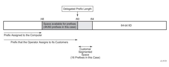
For example, a DHCPv6 server prefix pool contains an aggregated (configured) IPv6 prefix from which the delegated prefixes will be carved out. In Figure 68 this aggregated IPv6 prefix has length of /48. In addition, the DHCPv6 server needs to know the length of the delegated prefix (in the above case /60). These two values are marking the boundary within which a unique delegated prefix will be selected. This is represented by the purple area in Figure 68.
The delegated prefix length can be obtained via:
- RADIUS
- Delegated-IPv6-Prefix attribute that contains the prefix and the length (Delegated-IPv6-Prefix = AAAA:BBBB::/56). The DPL in this case is /56.
- Alc-Delegated-IPv6-Prefix-Length VSA (to be used in conjunction with the DHCPv6 pool name - Alc-Delegated-IPv6-Pool VSA)
- LUDB – configured via LUDB per IPoEv6/PPPoEv6 host:This is to be used along with the DHCPv6 pool name (ipv6-delegated-prefix-pool) defined under the same CLI hierarchy.
Alternatively, the entire prefix, including the DPL can be returned via LUDB.
- DHCPv6 server – each DHCPv6 pool can optionally be configured with a DPL:
- Configured statically under the ipv6 CLI node of subscriber-interface. In this case, the DPL is fixed for all subscriber hosts under the subscriber interface.
9.4.2.4.1. Order of Preference for DPL
In case that the DPL is statically provisioned under the subscriber-interface>ipv6> hierarchy, all hosts under this subscriber-interface will inherit this fixed DPL. In case that the DPL is provided via LUDB or RADIUS in addition to static configuration under the subscriber-interface then the LUDB or the RADIUS one MUST match the DPL that is statically provisioned under the subscriber-interface. Otherwise, the prefix instantiation in 7450 ESS and 7750 SR will fail.
Note that the “no delegated-prefix-length” command under the subscriber-interface>ipv6> hierarchy means that the DPL is set to a default-value of 64.
When the delegated-prefix-length commands under the subscriber-interface>ipv6> hierarchy is set to variable, prefixes under such subscriber-interface can have different lengths and the DPL can be configured via one of the following means:
- LUDB
- RADIUS
- DHCP Server
9.4.2.4.2. DHCP Server Address Utilization and Delegated Prefix Length
In case that the delegated prefix length is variable, for each consecutive address allocation request for the given delegated prefix, the DHCPv6 server will allocate the prefix at the end of the last delegated lease with the same delegated prefix length. This will minimize the address space fragmentation within the configured prefix.
9.4.2.5. DHCPv6 Relay Agent
A DHCPv6 Relay Agent can support a 7450 ESS and 7750 SR DHCPv6 local server (same or remote chassis) and a third party DHCPv6 external server.
An incoming DHCPv6 client message is relayed within the Relay-Forward message specified in RFC 3315. If the server responds with a valid address/prefix, the ESM process attempts to install it. If it fails, the DHCPv6 Relay Agent sends an explicit RELEASE to the server. There is no retransmission of DHCPv6 Relay-Forwards in the case of failure – it requires the client to re-start or re-send the original DHCPv6 message.
A Lightweight DHCPv6 Relay Agent may insert Relay Agent Information including the Interface ID option between the DHCPv6 client and the DHCPv6 Relay Agent.
Additional Relay Agents (non-LDRA) between the DHCPv6 client and the DHCPv6 Relay Agent are not supported.
9.4.2.5.1. Configuring a DHCPv6 Relay Agent
A DHCPv6 Relay Agent is configured in the IPv6 DHCP6 context of a group-interface:
Up to eight DHCPv6 servers can be provisioned to be served by a DHCPv6 Relay Agent. A Relay-Forward is send to all servers and the Relay-Replies from all servers are sent to the client.
The “client-applications” parameter specifies if the Relay Agent can be used for IPoE (dhcp) or PPP (ppp) hosts. Optional configuration parameters:
- description — A free configurable description string.
- link-address — The link address field in the DHCPv6 Relay-Forward message header.The link address can be configured to enable link-address based pool selection in a 7450 ESS and 7750 SR DHCPv6 local server. The address must be one of the IPv6 prefixes configured at the ipv6 subscriber-prefixes context for a subscriber interface. If not configured, the system selects one of the prefixes.
- option: allows to configure following options to be inserted in the Relay-Forward message:
- Interface-Id [18] — The interface ID option identifies the interface on which the DHCPv6 client message is received. The format options are the following:
- ascii-tuple: — host-name|service-id|group-interface-name|sap-id
- ifindex — Interface index for the group-interface
- sap-id — SAP identifier (port and vlans)
- string <string>: — A free configurable string (max. 80 chars)
- Remote-Id [37] — Relay Agent Remote Id option contains the DHCPv6 client DHCP Unique Identifier (DUID).
- source-address: the source-address of the Relay-Forward messages.If not configured, the outgoing interface IPv6 address is used. The source-address configuration is mandatory for a DHCP Relay Agent in a VPRN service when the DHCPv6 server is reachable via a tunnelled next-hop (MPLS).
9.4.2.6. DHCPv6 Relay to Third Party DHCPv6 External Server
When the DHCPv6 Relay Agent is relaying to a third party DHCPv6 external server, following conditions should be met:
- The third party DHCPv6 server must return a unique IA_PD IPv6 delegated prefix (/64 or lower) for each allocation. The length of the IA_PD IPv6 delegated prefix must match the delegated-prefix-len configured on the subscriber interface on the 7750 DHCP L3 relay. This length is also included in the Relay-Forward message as PFX_LEN option (3) in a Vendor-Specific-Information-Option (17).
- For IPv6oE routed CPE's, the 3rd party DHCPv6 server must return a unique IA_NA IPv6 address (/128) from a different /64 subnet for each allocation.
- For IPv6oE hosts behind bridged CPE's,
- the third party DHCPv6 server must return a unique IA_NA IPv6 address (/128) from a different /64 subnet for each allocation (host) that belongs to a different CPE.
- the third party DHCPv6 server may return a unique IA_NA IPv6 address (/128) from the same /64 subnet for allocations (hosts) that belong to the same CPE and that are attached to the same vlan (SAP) on the BNG.
Following information is available to the third party DHCPv6 server in a Vendor-Specific-Information-Option (17) included in the Relay-Forward message:
- WAN_POOL option (1) contains the pool name from which the IA_NA IPv6 address should be allocated.
- PFX_POOL option (2) contains the pool name from which the IA_PD IPv6 delegated prefix should be allocated.
- PFX_LEN option (3): contains the IA_PD IPv6 delegated prefix length that should be allocated.
9.4.2.7. DHCPv6 Local Server
A local DHCPv6 pool server for both addresses (IA_NA) and prefixed (IA_PD) manages the address and prefixes sent to either routing gateways or hosts.
Because IPv6 home networks lack NAT, the IPv6 addresses delegated to a routing gateway are in turn assigned to hosts in the home. These addresses are assigned with reasonably long (but configurable) lifetimes such that the loss of the WAN connection will not result in the IPv6 hosts in the LAN losing their IPv6 addresses. One consequence of these long lifetimes is that the IPv6 hosts will retain any IPv6 address provided the valid-lifetime is greater than zero. Should an operator delegate a prefix and then at a later time delegate a second IPv6 prefix, a host may end up with two or more valid prefixes. This situation plays havoc with IPv6 source address selection and may result in impaired service.
To overcome the problems of multiple IPv6 prefixes in the home, the operator must ensure that the individual subscriber has the same IPv6 prefix even across modem reboots (that is, if a subscriber session is destroyed and later re-created, an attempt should be made to use the previously delegated prefix). In release 8.0, the operator used RADIUS for all address and prefix assignment, but in release 9.0, with the introduction of the local DHCPv6 server, it requires the 7750 to process and maintain some state even after a session disconnects.
For the DHCPv6 local server to function, a DHCPv6 relay or proxy function must also operate alongside ESM. For the purposes of this document, to relay means to implement a DHCPv6 Relay as indicated in RFC 3315 : a relay encapsulates the client DHCP message within a DHCP Relay-Forward message and unicasts it to a specified destination.
A proxy is an internal concept. Unlike a DHCPv6 relay, the DHCPv6 proxy does NOT encapsulate the client message in a Relay-Forward, nor does it send packets towards the Local DHCPv6 Server. The DHCPv6 proxy is exclusively used as an interface between the RADIUS Access-Accept or local user database lookup and the DHCPv6 client in the consumer device.
The use of the DHCPv6 relay or proxy function depends on the attributes returned from authentication phase (RADIUS or LUDB).
- DHCPv6 Proxy:
- If only IPv6 address/prefix information provided (Framed-IPv6-Prefix, Alc-IPv6-Address or Delegated-IPv6-Prefix).
- DHCPv6 Relay:
- If no IPv6 address/prefix (Framed-IPv6-Prefix, Alc-IPv6-Address or Delegated-IPv6-Prefix) and no IPv6 pool (Framed-Pool, Delegated-Pool) information provided.
- If no IPv6 address/prefix (Framed-IPv6-Prefix, Alc-IPv6-Address or Delegated-IPv6-Prefix) and IPv6 pool (Framed-Pool, Delegated-Pool) information provided.
- If both IPv6 address/prefix (Framed-IPv6-Prefix, Alc-IPv6-Address or Delegated-IPv6-Prefix) and IPv6 pool (Framed-Pool, Delegated-Pool) information are present, the DHCP packet is DROPPED.
| Note: If IPv6 DNS parameters are returned in RADIUS AND a pool is specified then the DNS parameters are ignored. It is the DHCPv6 server that will need to reply with appropriate DNS servers. |
9.4.3. Dynamic Subscriber Host Processing
9.4.3.1. Dynamic Tables
To support all processing for Enhanced Subscriber Management, several tables are maintained in the router (Figure 69).
Figure 69: Enhanced Subscriber Management Dynamic Tables
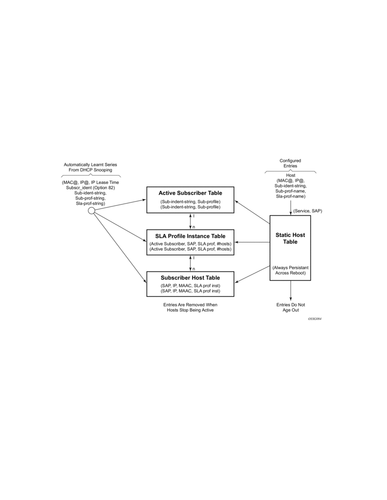
9.4.3.1.1. Active Subscriber Table
An entry is created in the active subscriber table when the first host (either dynamic or static) is created with a certain subscriber identification string. The entries are grouped by their subscriber identification string.
Fields for each entry in the active subscriber table include:
- The subscriber identification string (see Subscriber Identification String).
- In use subscriber profiles (see Subscriber Profile).
9.4.3.1.2. SLA Profile Instance Table
An entry is created in the SLA profile instance table when the first subscriber host on a certain SAP is created that uses a certain SLA profile. All subsequent hosts of the same subscriber on the same SAP that use the same SLA profile will be associated with this entry. When the last host on this SAP, using this SLA profile disappears, the SLA profile instance is deleted from the table and the associated queues are removed.
SLA profile instances can not span multiple subscriber SAPs. If subscriber hosts from the same subscriber exist on multiple SAPs and are associated with the same SLA profile template, a separate SLA profile instance is created for each SAP.
Fields for each entry in the SLA profile instance table include:
- Active subscriber
- SAP
- SLA profile
- Number of active subscriber hosts that share this instance
9.4.3.1.3. Subscriber Host Table
An entry is created in the subscriber host table if anti-spoofing is enabled as well as:
- The first host (dynamic or static) with a specific IP and MAC combination is created. If the anti-spoof is IP only, the MAC address is masked to all 0’s. If anti-spoof is MAC, only the IP address is 0.0.0.0. All dynamic hosts and static hosts with the same IP and MAC combination will be associated with the same subscriber host entry. If the anti-spoof type includes IP (IP-only or IP/MAC), there can be at most two hosts associated with the entry: one dynamic and one static. If the anti-spoof type is MAC-only, there can be a combination of several dynamic and static hosts associated with the entry.
- The non-prof-traffic is provisioned. Both IP and MAC address are all 0’s.
Fields for each entry in the subscriber host table include:
- SAP
- IP address
- MAC address
- SLA profile instance (enhanced mode only)
9.4.3.1.4. DHCP Lease State Table
An entry in the DHCP lease state table is created for each dynamic host. Fields for each entry in the lease state table include:
- Assigned IP address
- Assigned MAC address
- Persistence key
9.4.4. Enhanced Subscriber Management Entities
Figure 70 illustrates the relationship between the main entities in Enhanced Subscriber Management:
- A subscriber is associated with only one subscriber profile.
- A subscriber can be associated with one or more SLA profile (a VPLS service with 2 different SAPs can have different SLA profiles for the same subscriber).
- A maximum of one SLA profile instance is generated (including ingress and egress queues) per SAP per SLA profile.
- One or more hosts can be assigned to each SLA profile instance (these will share the same queues).
Figure 70: Relationship Between Enhanced Subscriber Management Entities
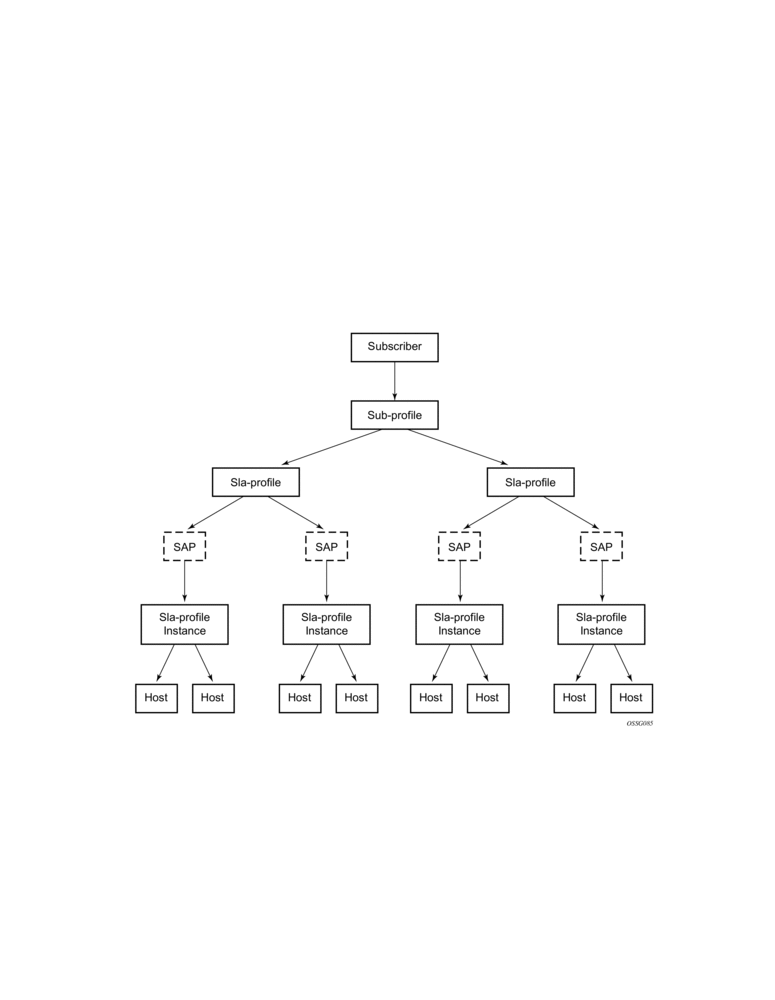
9.4.4.1. Instantiating a New Host
When a DHCP ACK is received for a new subscriber host on a particular SAP:
- The ACK message is parsed using the appropriate script.
- An entry is generated in the subscriber host table with indices:
- The SAP on which the host resides
- The assigned IP address
- The assigned MAC address and as lookup parameters:
- The subscriber profile and
- The SLA profile to be used (derived from using the script).
If this is the first host of a subscriber, an HQoS scheduler is instantiated using the ingress and egress scheduler policies referred to in the subscriber profile. Otherwise, if the subscriber profile of the new host equals the subscriber profile of the existing subscriber, the new host is linked to the existing scheduler. If the subscriber profile is different from the subscriber profile of the existing subscriber, a new scheduler is created and all the hosts belonging to that subscriber are linked to this new scheduler. Notice that the new subscriber profile will not conflict with the subscriber profile provisioned for a static host or non-sub-traffic under the same SAP.
If this is the first host of a subscriber on a particular SAP using a particular SLA profile, an SLA profile instance is generated and added to the SLA profile instance table. This includes instantiating a number of queues, according to the ingress and egress QoS profiles referred to in SLA profile, optionally with some specific overrides defined in the SLA profile. Otherwise the host is linked to the existing SLA profile instance for this subscriber on this SAP.
| Note: Any QoS and IP filter policies defined on the SAP are still processed even if Enhanced Subscriber Management is enabled on the SAP. For IPv4 traffic that is dropped due to anti-spoofing, counters, logging, and mirroring can be used. All other Layer 2 traffic that is never blocked by anti-spoofing can be processed by applying a QoS policy on the SAP and can still be classified differently, by the dot1p value. |
| Note: If insufficient hardware resources (queues) or software resources (profile instances) are available to support the new host, the DHCP ACK is dropped and an event is generated. |
9.4.4.2. Packet Processing for an Existing Host
Whenever an IP packet arrives on a subscriber-facing SAP on which Enhanced Subscriber Management is enabled, a lookup is done in the subscriber host table using as the index the SAP, source IP address, and source MAC address.
- If there is no entry, this means that the host is not using his assigned IP address, so the packet is dropped;
- If there is an entry, this will refer to the subscriber profile and SLA profile to be used.
9.4.5. ESM Host Lockout
This feature increasingly penalizes hosts that fail repeated login attempts within a configurable time interval. This is done by holding off on creation attempts for these hosts for a configured but adaptable time period. A transient failure, due to a mis-configuration, is quickly corrected and does not prevent the host from logging in within a reasonable amount of time. At the same time, a malicious client or a constantly mis-configured client is locked-out and will not take up resources impacting other clients.
A lockout time per host supports exponential back-off with each retry and failure cycle, starting with a configured minimum value and increasing up to a configured maximum. The lockout time can be reset to the configured minimum value if there is no failed retry within a configured time threshold. The configurable values include:
If multiple retries/failure cycles occur within the lockout time, then lockout period is exponentially increased starting from configured minimum value up to the configured maximum value. The lockout is reset to the minimum value if there is no failed retry till this lockout time.
This mechanism is supported for both single and dual-stack PPPoE and IPoE (DHCP) hosts over 1:1 or N:1 static or managed SAPs. The hold-off timer maintenance is on a per host basis (as follows):
- For 1:1 VLAN (PPPoE or IPoE hosts) per <VLAN, MAC address>
- For N:1 VLAN (PPPoE or IPv4oE hosts) per <VLAN, agent-circuit-id, agent-remote-id, MAC@>
- For 1:1 VLAN (IPv6oE hosts) per <VLAN, DUID>
A show lockout state for hosts is supported, given one or more of <SAP, MAC@, agent-circuit-id, agent-remote-id>.
A clear lockout state is supported for hosts given one or more of <SAP, MAC@, agent-circuit-id, agent-remote-id>.
Any changes in configured lockout values will not apply to hosts currently under lockout and will only apply once these hosts are out of lockout.
9.4.5.1. Functionality
ESM lockout is supported for dual-stack PPPoE hosts, L2TP LAC hosts, dual-stack IPoE hosts, and ARP hosts. ESM Lockout tracks the following:
- PPPoE PADI and PADR
- DHCPv4 discover, DHCPv4 request, DHCPv6 solicit, DHCPv6 request
- ARP Request
- PPPoE session disconnect after successful session establishment
During lockout, authentication and ESM host creation is suppressed. A lockout context will be created when a client first enters lockout. The context maintains state and timeout parameters for the lockout. If a lockout policy is configured for the underlying SAP for a host that has failed authentication or host creation, the host enters lockout for the configured minimum time (1 to 86400 seconds). When the lockout time expires, normal authentication and ESM host creation will be resumed on relevant PPP or DHCP messages. In case of another failure, the host will again enter the lockout state. The lockout time for the host on each failure will be exponentially increased up to the configured maximum time (1 to 86400 seconds). The lockout time for a client will be reset to the configured minimum value, and the corresponding lockout context will be deleted, if there is no authentication (and host creation) failure within a configured amount of time that needs to elapse after the client initially enters lockout. This time is called the lockout-reset-time.
The host identification for lockout includes <SAP, MAC@, circuit ID, remote ID>.
9.4.6. ANCP and GSMP
9.4.6.1. ANCP
Access Node Control Protocol Management (ANCP) can provide the following information to the router:
- ANCP can communicate the current access line rate to the router. This allows the router to adjust the H-QoS subscriber scheduler with the correct rate or potentially change alarm when the rate goes below a set threshold. This allows a policy manager to change the entire policy when the rate drops below a minimal threshold value. The ANCP actual upstream synchronization rate is mapped to the ingress while ANCP actual downstream synchronization rate is mapped to the egress.
- The router can send DSL line OAM commands to complete an OAM test from a centralized point or when operational boundaries prevent direct access to the DSLAM.
When ANCP is used with Enhanced Subscriber Management (ESM), a new string ancp-string can be returned from the Python script or from RADIUS. If not returned it defaults to the subscriber ID.
ANCP version 0x31 and 0x32 are both supported and will be auto detected at the start of each ANCP session. Within version 0x32, partitioning is also supported.
Multiple partitions from the same Access Node are also supported. If partitions are used, they are automatically detected during the start of an ANCP session.
9.4.6.1.1. Static ANCP Management
As depicted in Figure 71, a DSLAM is connected to an aggregation network that is connecting the DSLAM to a BRAS. ANCP is used to provide SAP level rate management. The DSLAM in this application maintains multiple ANCP connections. The primary connection is to the BRAS, providing rate and OAM capabilities while the secondary is to the router to provide rate management.
7750 SR and 7450 ESS:
Figure 71: Static ANCP Management Example
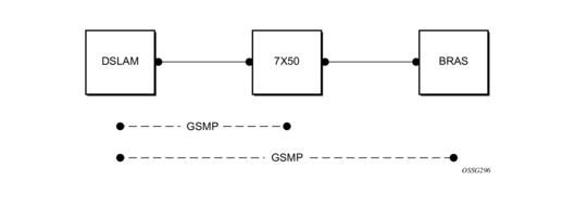
9.4.6.1.2. Enhanced Subscriber Management (ESM) Dynamic ANCP
In this application ANCP is used between the DSLAM and the router to provide line control. There are multiple attributes defined as described below. Figure 72 depicts the connectivity model.
This application is used to communicate the following from the DSLAM to the router (the policy control point):
- Subscriber rate
- OAM
Figure 72: ESM Dynamic ANCP Example
9.4.6.1.3. ANCP String
To support node communication with the access device the line rate, OAM commands, etc. the node can use an “ANCP string” that serves as a key in the out-of-band channel with the access node. The string can be either provisioned in the static case, retrieved from RADIUS or from the Python script.
9.4.6.1.4. ANCP Persistency Support
Persistency is available for subscriber’s ANCP attributes and is stored on the on-board compact flash card. ANCP data will stay persistence during an ISSU as well as nodal reboots. During recovery, ANCP attributes are first restored fully from the persistence file and incoming ANCP sessions are temporarily on hold. Afterwards new ANCP data can overwrite any existing values. This new data is then stored into the compact flash in preparation for the next event.
9.4.6.2. General Switch Management Protocol Version 3 (GSMPv3)
General Switch Management Protocol version 3 (GSMPv3) is a generic protocol that allows a switch controller node to establish and maintain connections with one or more nodes to exchange operational information. Several extensions to GSMPv3 exist in the context of broadband aggregation. These extensions were proposed to allow GSMPv3 to be used in a broadband environment as additional information is needed to synchronize the control plane between access nodes (such as DSLAMs) and broadband network gateways (such as BRAS).
In the TPSDA framework, nodes fulfill some BRAS functionality, where per subscriber QoS enforcement is one of the most important aspects. To provide accurate per-subscriber QoS enforcement, the network element not only knows about the subscriber profile and its service level agreement but it is aware of the dynamic characteristics of the subscriber access circuit.
The most important parameters in this context are the subscriber-line capacity (DSL sync-rate) and the subscriber's channel viewership status (the actual number of BTV channels received by the given subscriber in any point in time). This information can be then used to adjust parameters of aggregate scheduling policy.
Besides, the above-mentioned information, GSMPv3 can convey OAM information between a switch controller and access switch. The node can operate in two roles:
- As the intermediate controller — The router terminates a connection from the DSLAM.
- As the terminating controller— The router fulfils full the roll of BRAS.
The DSL forum working documents recommends that a dedicated Layer 2 path (such as, a VLAN in an Ethernet aggregation network) is used for this communication to provide a certain level of security. The actual connection between DSLAM and BRAS is established at TCP level, and then individual messages are transported.
9.4.6.3. DHCP Release Messages
The node supports DHCP release messages. A DHCP release message removes state from the DHCP server when the node rejects ACKs or removes hosts.
9.4.6.3.1. DHCP Release
DHCP release messages will be controlled by the node and sent to the DHCP server to clear stale state. There are two examples:
- If the node drops a DHCP ACK (because of resources, duplicate host or other reasons) the servers state must be cleared and the node will send a DHCP release.
- When a host state is removed, based on SHCV, ANCP, user clear, etc., the node will send a DHCP release to the server and the MAC will be flushed from SDPs. A new flag will allow the user to elect not to send the release message If when using a clear lease command the host was removed by the user (using a clear command) a new flag will allow the user to elect not to send the release message.
9.4.6.4. DHCP Client Mobility
Client mobility allows the node to use host monitoring (SHCV, ANCP, split DHCP) to remove network and server state when a host is removed locally. This allows for MAC addressed learned and pinned to move based on policy parameters.
Subscriber Host Connectivity Verification (SHCV) configuration is mandatory. This allows clients to move from one SAP to another SAP in the same service. This is only applicable in a VPLS service and group interfaces.
The first DHCP message on the new SAP with same MAC address (and IP address for group-interfaces) will trigger SHCV and will always be discarded.
SHCV will check that the host is no longer present on the SAP where the lease is currently populated to prevent spoofing. When SHCV detects that the host is not present on the original SAP, the lease-state will be removed. The next DHCP message on the new SAP can initiate the host.
9.4.6.5. DHCP Lease Control
DHCP lease control allows the node to be configured to present a different lease to the client. This can be used to monitor the health of the client.
9.4.7. Using Scripts for Dynamic Recognition of Subscribers
Whenever a host belonging to a subscriber is activated (when a PC or set-top box (STB) is turned on), the host will typically request an IP address from the network using DHCP. Refer to DHCP Management for an explanation of DHCP and DHCP snooping in the router.
The DHCP ACK response from the DHCP server can be parsed and the contents of the message can be used to identify the “class” to which this host belongs, and thus, the QoS and security settings to apply.
The information necessary to select these settings can be codified in, the IP address by the DHCP server and/or the Option 82 string inserted by the DSLAM or other access node.
9.4.7.1. Python Language and Programmable Subscriber Configuration Policy (PSCP)
PSCP is an identification mechanism using the Python scripting language. The PSCP references a Python script that can use regular expressions to derive the sub-ident-string, sub-profile-string and sla-profile-string from the DHCP response. A tutorial of regular expressions is beyond the scope of this guide, and can be found on the Internet (refer to http://www.amk.ca/python/howto/regex/).
A tutorial of Python is beyond the scope of this guide but can be found on the Internet (refer to http://www.python.org/).
Example scripts, using some regular expressions, can be found in Sample Python Scripts. Additional information about the service manager scripting language, see Python Script Support for ESM.
One or more scripts can be written by the operator and stored centrally on a server (in a location accessible by the router). They are loaded into each router at bootup.
Note that if a centrally stored script is changed, it is not automatically re-loaded onto the router. The reload must be forced by executing the shutdown / no shutdown commands on the affected URL(s).
9.4.7.2. Determining the Subscriber Profile and SLA Profile of a Host
Figure 73 describes the data flow while determining which subscriber profile and SLA profile to use for a certain subscriber host based on a snooped/relayed DHCP ACK for that subscriber host.
Figure 73: Data Flow in Determining Subscriber Profile and SLA Profile
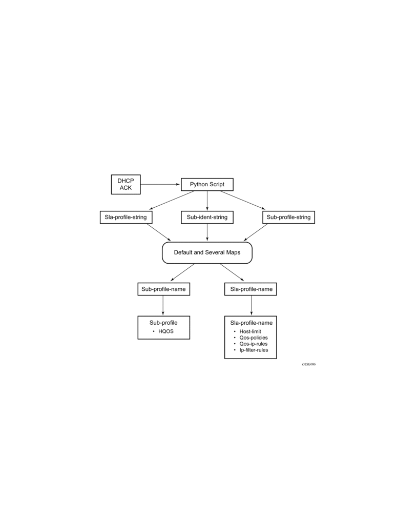
An incoming DHCP ACK (relayed or snooped) is processed by the script provisioned in the sub-ident-policy defined in the SAP on which the message arrived. This script outputs one or more of the following strings:
- sub-ident — Identifies the subscriber (always needed).
- sub-profile — Identifies the subscriber class (optional).
- sla-profile — Identifies the SLA Profile for this subscriber host (optional).
These strings are used for a lookup in one or more maps to find the names of the sub-profile and sla-profile to use. If none of the maps contained an entry for these strings, the names will be determined based on a set of defaults.
Only when the names for both the sub-profile and sla-profile are known, the subscriber host can be instantiated. If even no default is found for either profile, the DHCP ACK is dropped and the host will not gain network access.
9.4.7.3. Determining the Subscriber Profile
All hosts (devices) belonging to the same subscriber will be subject to the same HQoS processing. The HQoS processing is defined in the sub-profile. A sub-profile refers to an existing scheduler policy and offers the possibility to overrule the rate of individual schedulers within this policy.
Because all subscriber hosts of one subscriber use the same scheduler policy instance, they must all reside on the same I/O module.
The figure below shows how the sub-profile is derived, based on the sub-ident string, the sub-profile string and/or the provisioned data structures. The numbers associated with the arrows pointing toward the subscriber profiles indicate the precedence of the checks.
Figure 74: Determining the Subscriber Profile
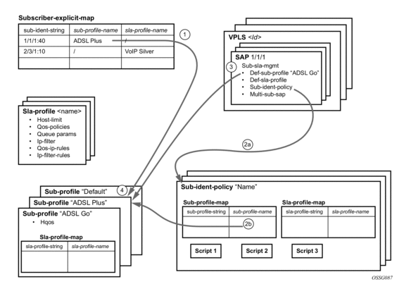
- A lookup in the explicit-subscriber-map is done with the sub-ident string returned by the script. If a matching entry is found, the sub-profile-name (if defined) is taken. Otherwise:
- If a sub-ident-policy is defined on the SAP, a lookup is done on its sub-profile-map with the sub-profile string from the script. The sub-profile-name is taken from the entry.If no entry was found, then:
- If provisioned, the sub-profile-name is taken from the def-sub-profile attribute on the SAP. If not provisioned, then:
- The sub-profile with the name “default” is selected (if provisioned). If this is not provisioned, there are no other alternatives, the ACK is dropped, and the host will not gain access.
9.4.7.4. Determining the SLA Profile
For each host that comes on-line, the router also needs to determine which SLA profile to use. The SLA profile will determine for this host:
- The QoS-policies to use:
- classification
- queues/policers
- queue mapping
- The egress scheduling policies to use:
- egress HQoS
- The IP filter to use.
The SLA profile also has a host-limit attribute which limits the number of hosts (belonging to the same subscriber) on a certain SAP that can be using this SLA profile.
The classification and the queue mapping are shared by all the hosts on the same forwarding complex that use the same QoS policy (by their SLA profile).
The queues/policers are shared by all the hosts (of the same subscriber) on the same SAP that are using the same SLA profile. In other words, queues/policers are instantiated when, on a given SAP, a host of a subscriber is the first to use a certain SLA profile. This instantiation is referred to as an SLA profile instance. Ingress queues can be parented to a scheduler referenced in the ingress of a subscriber profile. Egress policers and queues can be parented to a scheduler referenced in the egress of a subscriber or SLA profile, or to a port scheduler.
A scheduler policy can be applied to the egress an SLA profile, allowing its schedulers to be the parent for its queues and for its tier 1 schedulers to be parented to a scheduler in a scheduler policy applied to the egress of a subscriber profile or a vport, or to a port scheduler applied to a port or vport. Configuring scheduler overrides is allowed for SLA profile egress schedulers. The configuration of a scheduler policy in the egress of an SLA profile is supported for all host types only on Ethernet interfaces on FP2 and higher hardware. It is not supported for ESM over MPLS pseudowires, nor is HQoS adjustment and host tracking supported on its schedulers.
The following show/monitor/clear commands are available related to the SLA profile scheduler:
The show qos scheduler-hierarchy subscriber command (shown above) displays the scheduler hierarchy with the SLA profile scheduler as the root. Note that if the SLA profile scheduler is orphaned (that is when the scheduler has a parent which does not exist) then the hierarchy is only shown when the show command includes the sla-profile and sap parameters.
Note: If the SLA profile scheduler is orphaned (that is when the scheduler has a parent which does not exist) then the hierarchy is only shown when the show command includes the sla-profile and SAP parameters.
The figure below shows a graphical description of how the SLA profile is derived based on the subscriber identification string, the SLA profile string and the provisioned data structures. The numbers on the arrows towards the SLA profile indicate the priority of the provisioning (the lower number means the higher priority).
Figure 75: Determining the SLA Profile
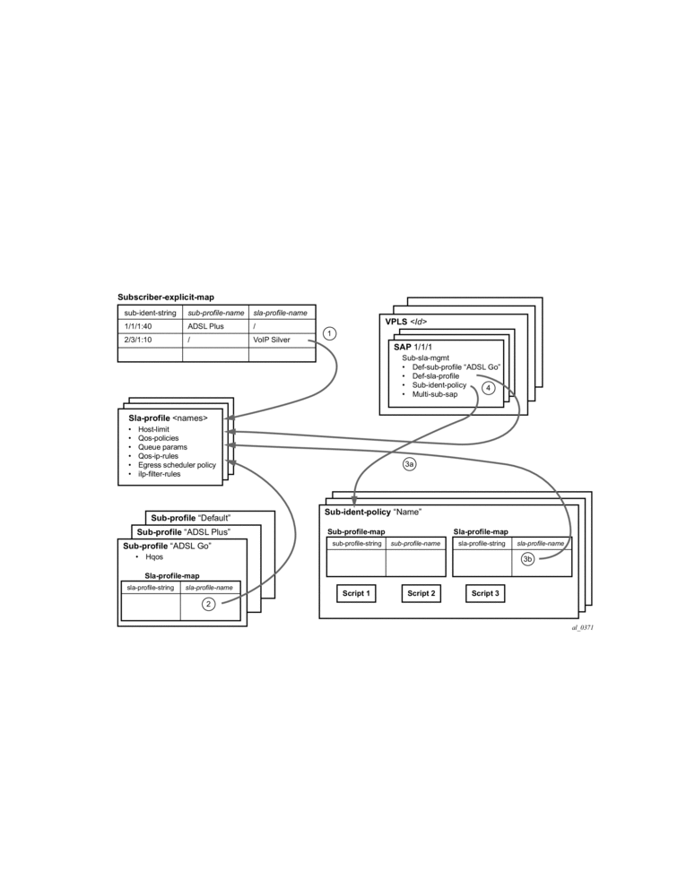
- A lookup is done with the sub-ident string returned by the script in the explicit-subscriber-map. If a matching entry is found, the sla-profile-name is taken from it – if defined. Otherwise:
- A lookup with the sla-profile string from the script is done in the sla-profile-map of the sub-profile found earlier. The sla-profile-name from the found entry is taken. If no entry was found, then:
- A lookup is done with the sla-profile string in the sla-profile-map of the sub-ident-policy configured on the SAP. The sla-profile-name from the found entry is taken. If no sub-ident-policy was configured on the SAP or no entry was found, then:
- If provisioned, the sla-profile-name is taken from the def-sla-profile attribute on the SAP. If not provisioned, there are no more alternatives, the ACK is dropped, and the host will not gain access.
9.4.7.4.1. SLA-Based Egress QoS Marking
The egress QoS marking for subscriber-host traffic is derived from SAP-egress QoS policy associated with a corresponding SAP, rather than from the SLA profile associated with the corresponding subscriber-host. As a consequence, no egress QoS marking (or Dot1p marking is set to 0, the dscp/prec field is kept unchanged) is performed for traffic transmitted on a managed-SAP because per default, sap-egress policy 1 is attached to every managed-SAP.
The default value of the “qos-marking-from-sap” flag is enabled. This means that the qos-marking defined in the SAP egress QoS policy associated with the SAP will be used. The default setting of this flag in a combination with managed-SAP will result in the same behavior as in the current system (dot1p=0, dscp/prec is unchanged).
If “no qos-marking-from-sap” is executed, then both the Dot1p marking (all IOMs) and DSCP marking (IOM2/3 only) are derived from the sla-profile.
Changing the flag setting in the SLA profile being used by any subscriber-hosts (this includes subscriber-hosts on managed-SAPs as well) will be allowed.
The following MC traffic characteristics apply:
- On Layer 3 subscriber-interfaces, MC is not supported so it is impossible to enable it at the SAP level or at the sla-instance level.
- On Layer 2 SAPs IGMP snooping is supported while it is not supported on the sla-instance level. Therefore, any MC traffic transmitted at egress belongs to a SAP (meaning it will use SAP queues), rather than to sla-instance.
- The special case are SAPs with a profiled-traffic-only flag enabled. Although it is possible to define an sla-profile applicable to a Layer 2-host, this will not be taken as reference for marking mc-traffic, but rather SAP settings will be used.
9.4.8. Auto-Sub ID
The subscriber ID name (sub-id) is a mandatory object that binds all hosts of a given subscriber together. Briefly, the sub-id name represents a residential household. Many management/troubleshooting and even billing operations rely on the sub-id name entity. The sub-id name is required for the host creation process, and it can be supplied by RADIUS or LUDB. It is derived from the sap-id or is statically provisioned in the form of a string.
In many ESM deployments with RADIUS, it is desirable that the sub-id is auto-generated within the 7450 ESS and 7750 SR rather than burdening the OSS and the RADIUS server with this function. A typical application for auto sub-id is as follows:
- RADIUS server provides the sla-profile string and the sub-profile string but not the sub-id string.
- The sub-id name is auto-generated and formatted based on the configured options.
The following are the properties of auto sub-id generation:
- The auto-generation of the sub-id name can be based on any combination of the following fields:
- MAC address
- sap-id
- circuit-id
- remote-id
- session-id
There can be only a single set of subscriber identification fields defined per host type (IPoE or PPPoE) per chassis. If the combination of the fields must be modified, the existing subscribers with an auto-generated sub-id must be manually terminated. Considering that remote termination of the IPoE subscribers by a DHCP server is not supported by all DHCP client vendors through the FORCERENEW DHCP message (RFC 3203, DHCP reconfigure extension), changing the subscriber fields while subscribers with auto generated sub-id are active should be avoided.
The sub-id name generation will take place at the end of the host initiation process (as after the authentication phase is completed) and only in case whereby the sub-id had not been already provided by any other more specific means (RADIUS, LUDB). This means that if the sub-id is supplied by other means (RADIUS, LUDB), then the sub-id name will not be auto-generated.
The format of the sub-id name can be either a random 10 characters encoded string or a user- friendly string based on the subscriber identification fields. Note that the maximum length of the sub-id name is 32 characters.
The sub-id name will not be passed in the Access-Request to the RADIUS server since it is generated after the authentication phase.
The sub-id name can be auto-generated regardless of how the sla/sub-profile strings are obtained (RADIUS, LUDB or static).
The subscriber identification fields used in auto-generation of the sub-id name are enabled on the global level.
If no sub-id-key per host type is configured, then the defaults are:
PPPoE host type: | <mac, sap-id, session-id> |
IPoE host type : | <mac, sap-id>. |
The order in which the fields are configured is important because the sub-id name will potentially become a concatenated string of the subscriber host identifiers in the order in which they are provisioned. Note that the sub-id cannot be longer than 32 characters.
- In case that the length of the concatenated fields for the sub-id name is larger than 32 characters, the host creation will fail.
- In case that the circuit-id/remote-id is in the key and they contain non-printable characters, their place in sub-id name will be formatted in hex instead of ASCII. ASCII printable characters contain byte values 0x20..0x7E. All other values are ASCII non-printable and thus are formatted in hex characters.
The following would generate a sub-id name: xx:xx:xx:xx:xx:xx|1/1/3:23|44. The length of such sub-id name would be 29B.
- mac: xx:xx:xx:xx:xx:xx
- sap: 1/1/3:23
- session-id: 44 (16bits length)
In case that the key contains the circuit-id as: 0x610163 (3 bytes), then the sub-id name will be formatted as ‘610161’ (hex) since ‘01’ hex is non printable in ASCII. In this case the sub-id name will be of length 6B.
However, if the circuit-id is 0x616263 (3 bytes), then the string will be formatted as ASCII string ‘abc’ (3 characters). The sub-id name is 3B long.
The assignment of the sub-id to dynamic hosts is as follows:
- From RADIUS (sub-ident-policy including use-direct-map-as-default)
- From LUDB (sub-ident-policy including use-direct-map-as-default)
- Configured (explicit) defaults:
- use-sap-id: sap-id
- auto-id: combination of sub-id identifiers specified in auto-sub-id-key. The sub-id name will be in a human friendly format, i.e. concatenation of the fields in the pppoe|ipoe-sub-id-key command separated by a “|” character.
- string: custom string
- Non-configured (implicit) defaults:PPPoE host types: random 10 character string based on fields defined in the
- ppp-sub-id-key command. If no such fields are explicitly defined, the default ones will be assumed: <mac, sap-id, session-id>.
- IPoE host types: random 10 character string based on the ipoe-sub-id-key command. If no such fields are explicitly defined, the defaults will be assumed: <mac, sap-id >.
The way in which the default sub-id is generated is configured under the SAP level in the following manner:
Under the msap-policy:
The use-auto-id keyword parameter of the def-sub-id string consists of concatenated auto-sub-id-keys separated by a ‘|‘ character. In the absence of the use-auto-id keyword, the sub-id name will be a random 10 characters encoded string based on the ipoe|ppp-sub-id-keys. This random encoded 10 character string is unique per chassis as well as in dual-homed environment.
This command will have no effect if it is configured directly under the capture SAPs in VPLS (in the config>service>vpls>sap>sub-sla-mgmt context). Managed SAPs in ESM are instantiated by a capture SAP and the msap-policy in this case is mandatory. An auto-id keyword in case of managed SAP will be looked only under the msap-policy.
Static subscribers are required to have the sub-id manually configured.
9.4.8.1. Sub-id Identifiers
The sub-id can be based on any combination of the following identifiers:
- The sap-id, in combination with any other allowable identifier, will be used as the search key. This assumes a 1:1 (subscriber per SAP) deployment model.
- The circuit-id, in combination with any other allowable identifier, will be used to identify subscribers. This can be used in 1:1 deployment model, or in service per SAP deployment model. Circuit-id is applicable to IPoE v4 type hosts (option 82), to IPoE v6 type hosts (option 18 – interface-id) and PPPoE hosts (remote agent option signaled by PPPoE tags). The format of circuit-id is identical for IPv4 and IPv6 hosts.
- The remote-id, in combination with any other allowable identifier, will be used to identify subscribers. This can be used in 1:1 deployment model, or in service per SAP deployment model. The remote-id is applicable to IPoE v4 type hosts (option 82), to IPoE v6 type hosts (option 37) and PPPoE hosts (remote agent option signaled via PPPoE tags).
- The mac address (in combination with any other allowable identifier will be used to identify subscribers. This assumes a 1:1 deployment model.
- The PPPoE session id, in combination with any other allowable identifier, is applicable only to PPPoE hosts. The session-id used will be of the first host that is instantiated for the subscriber.
9.4.8.2. Dual Stack Hosts
Auto-generation of sub-id names for subscribers with a single dual stack hosts (IPoE and PPPoE) is enabled by default by not explicitly provisioning anything for the def-sub-id. The sub-id name would be semi-randomly generated based on the <mac, sap-id, session-id> for PPPoE hosts and the <mac, sap-id> combination for IPoE host.
9.4.8.3. Mixing Hosts with Auto-Generated IDs and non Auto-Generated IDs
Hosts with different sub-id names but identical auto-sub-id keys are not linked into the same subscriber. Such scenarios can arise with hosts with the same auto-sub-id keys but different methods for obtaining the sub-id name. For example, one host relying on auto-generated sub-id name while the other is using explicit configuration methods (sap-id, string, RADIUS or LUDB). If the auto-generated sub-id name and explicit sub-id name are the same, the host will be tied into the same subscriber.
For example:
The default auto-sub-id for the following two hosts are <mac, sap-id>.
Host X on SAP 1/1/1:1 with MAC 00:00:00:00:00:01 obtains sub-id through RADIUS.
Host Y on SAP 1/1/1:1 with MAC 00:00:00:00:00:01 has sub-id auto-generated.
Regardless of which host comes up first, those two hosts at the end will belong two different subscribers as long as their sub-ids are different.
9.4.8.4. PPPoA/PPPoEoA Considerations
PPPoA/PPPoEoA hosts will adhere to the same rules as PPPoE. Fields that are supported in PPPoE but not PPPoA/PPPoEoA will be simply ignored.
Fields that are not supported in PPPoA are:
- Remote-id
- Circuit-id
- MAC address
Fields that are most likely not applicable to PPPoEoA are:
- Remote-id
- Circuit-id
9.4.8.5. Deployment Considerations
The following is a possible deployment example scenario.
Assume the following cases:
- RADIUS returns the sub-id on all four SAPs.
- RADIUS does not return the sub-id string on any of the SAPs.
In the first case where RADIUS returns the sub-id string, the following will occur:
- On all 4 SAPs the sub-id string will be assigned by the RADIUS server. Defaults have no effect, and neither do identifiers specified under the auto-sub-id-key node.
In the second case, the effects are the following:
- On SAP1 the sub-id name will be the <sap-id> (1/1/1:3)
- On SAP 2 the sub-id name will be <sap-id> for PPPoE hosts and <mac>-<circuit-id> concatenation for IPoE type hosts.
For example:
1/1/1:100 for PPPoE
AC:AB:AA:AD:AE:AE-AN-id eth 1/1/1/1:2 for IPoE
(circuit-ID format is: Access-Node-Identifier atm slot/port:vpi.vci or Access-Node-Identifier eth slot/port:[vlan-id]).
Note that the circuit-ID can itself be 63B in length whereas the length of the sub-id name is limited to 32 Bytes. So in the above case, the sub-id name length would be 38 Bytes (>32B) and the host instantiation would fail.
- On SAP3 the sub-id name will be the literal ‘sub3’ for PPPoE and IPoE hosts.
- On SAP4 the sub-id name will be a semi-random value based on <sap-id> for PPPoE hosts and the <mac, circuit-id> combination for IPoE hosts.
9.4.8.6. Caveats
Only a single combination of the subscriber fields used to auto generate sub-id is allowed per host type (IPoE or PPPoE) and per chassis. In case that the combination of the fields needs to be changed, the existing subscribers with an auto-generated sub-id must be manually terminated. Considering that remote termination of the IPoE subscribers by DHCP server is not supported by all DHCP client vendors through FORCERENEW DHCP message (RFC 3203), changing the subscriber fields while subscribers with auto generated sub-id are active should be avoided.
9.4.9. Limiting Subscribers and Hosts on a SAP
A number of configuration parameters are available to control the maximum amount of subscribers and/or hosts that can be simultaneously active on a SAP:
- multi-sub-sap — Limits the number of subscribers (dynamic + static) on a SAP
- lease-populate — Limits the number of dynamic hosts on a SAP
- host-limit — Limits the number of hosts (dynamic + static) per SLA profile instance.
If any of these limits are reached, a new host will be denied access. The only exception is when host-limit command is configured with the keyword remove-oldest specified, then the oldest active host is dropped and the new host is granted access. The dynamic host with the least remaining lease time will be considered the oldest host. Note that remove-oldest only applies to DHCP and ARP-host, and it is not for PPPoE or IPv6 ESM hosts.
9.4.10. Static Subscriber Hosts
While it is typically preferred to have all hosts provisioned dynamically through DHCP snooping, it may be needed to provide static access for specific hosts (those that do not support DHCP).
Since a subscriber identification policy is not applicable to static subscriber hosts, the subscriber identification string, subscriber profile and SLA profile must be explicitly defined with the host’s IP address and MAC address (if Enhanced Subscriber Management is enabled).
If an SLA profile instance associated with the named SLA profile already exists on the SAP for the subscriber, the static subscriber host is placed into that SLA profile instance. If an SLA profile instance does not yet exist, one will be created if possible. If the SLA profile cannot be created, or the host cannot be placed in the existing SLA profile instance (the host-limit was exceeded), the static host definition will fail.
9.4.11. QoS for Subscribers and Hosts
9.4.11.1. QoS Parameters in Different Profiles
QoS aspects for subscribers and hosts can be defined statically on a SAP or dynamically using
Enhanced Subscriber Management. For example, in a VLAN-per-service model, different services belonging to a single subscriber are split over different SAPs, and thus the overall QoS (such as a scheduler policy) of this subscriber must be assigned using Enhanced Subscriber Management.
QoS parameters are shared among the subscriber profile and SLA profile as follows:
- The subscriber profile refers to HQoS ingress and egress scheduler policies which define the overall treatment for hosts of this subscriber when queues are used, or policers managed by HQoS are used at egress. If the subscriber is using policers, the subscriber profile also refers to CFHP ingress and egress policer-control-policies which define the overall treatment for hosts of this subscriber.
- The SLA profile refers to specific queue/policer settings for each host (BTV, VoIP, PC) using SAP ingress and SAP egress QoS policies. The SLA profile can also refer to an egress HQoS scheduler policy which defines the scheduling from the queues of the related host.
The primary use of the subscriber profile is to define the ingress and egress scheduler policies/ policer-control-policies used to govern the aggregate SLA for all hosts associated with a subscriber. To be effective, the queues/policers defined in the SLA profile’s QoS policies will reference a scheduler/arbiter from the scheduler policy/policer-control-policy respectively as their parent.
9.4.11.2. QoS Policy Overrides
Generic QoS queue/policer parameters could be specified for the SAP in a QoS policy and overridden for some customers by queue/policer parameters defined in the SLA profile. This allows for a single SAP ingress and SAP egress QoS policy to be used for many subscribers, while providing individual subscriber parameters for queue/policer operation.
9.4.12. ESM Subscriber Hierarchical Traffic Control
ESM subscribers can make use of both queues and/or policers for both the ingress and egress traffic. The queue and policers are configured within SAP ingress/egress policies applied to the SLA profile. The policers (at egress only) queue can parent to different levels/cir-levels with different weights/cir weights of a virtual scheduler configured within a scheduler policy, and to an egress port scheduler configured in a port scheduler policy, to achieve hierarchical traffic control. The policers can parent to different levels with different weights of an arbiter configured within a policer control policies to achieve hierarchical traffic control.
9.4.12.1. Subscriber HQoS
Hierarchical QoS (HQoS) corresponds to scheduling bandwidth distribution to policers, queues and schedulers and is applied using scheduler policies at ingress and egress of the subscriber profile for a subscriber, and at egress in the SLA profile for a host, together with a port scheduler at both the port and vport level.
Each scheduler policy can contain up to three tiers of schedulers with lower level schedulers being able to parent to higher level schedulers in the same scheduler policy.
Policers and queues can parent to any scheduler in their related scheduler policy hierarchy (except vport at egress) and also at the egress to a port scheduler.
Schedulers can parent to any higher level scheduler in their related scheduler policy hierarchy and, at the egress to a port scheduler configured within the port or vport. When an egress port scheduler is used, an aggregate rate limit can be applied at the subscriber profile and vport levels instead of using a scheduler. To extend the hierarchy further at egress, a tier 1 scheduler within a scheduler policy can parent to any scheduler in a scheduler policy at a higher level.
The scheduling levels are comprised of:
- Ingress and egress queues
- Egress policers
- Egress SLA-profile schedulers
- Ingress and egress subscriber profile schedulers
- Egress vport schedulers
- Port schedulers
The ingress hierarchical parenting relationship options are shown in Figure 76.
Figure 76: Ingress Scheduling Hierarchy Options
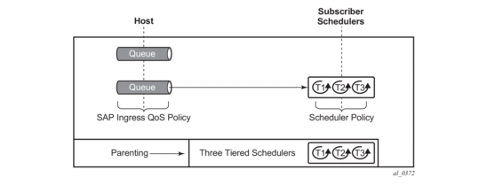
The egress hierarchical parenting relationship options are shown in Figure 77. Note that not all combinations can be configured concurrently, and some uses of port parent could be equally achieved using a scheduler parent and a child parent-location.
Figure 77: Egress Scheduling Hierarchy Options
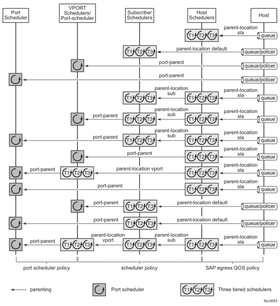
The parent command is used to specify the name of the parent scheduler when parenting a queue or scheduler, together with the level/cir-level and weight/cir-weight at which to connect.
The location of the parent scheduler (in which applied scheduler policy it exists) for a policer or queue defaults to a scheduler in the subscriber ingress or egress scheduler policy. Parents of schedulers themselves must be explicitly configured and by default must be within the same scheduler policy.
At egress, the scheduler parenting relationship is determined using the parent-location command:
By default, egress queues parent to any scheduler in subscriber egress scheduler policy.
Egress queues can parent to any scheduler within the scheduler policy applied to the egress of an SLA profile (this is not supported for policers managed by HQoS).
By default, a tier 1 scheduler in the scheduler policy is not allowed to be parented to another scheduler.
A tier 1 scheduler in the scheduler policy applied to the egress of an SLA profile can parent to a scheduler applied to the egress of a subscriber profile.
A tier 1 scheduler in the scheduler policy applied to the egress of a subscriber profile can parent to a scheduler applied to the egress of a Vport.
The configuration of a parent-location and frame-based accounting in a scheduler policy is mutually exclusive in order to ensure consistency between the different scheduling levels.
Note that the parent-location command is supported only on Ethernet interfaces on FP2 and higher hardware. It is not supported for ESM over MPLS pseudowires.
Both egress queues and egress schedulers can port parent using directly to different levels/cir-levels, with different weights/cir weights, to a port egress port scheduler. Egress schedulers can also port parent directly to different levels/cir-levels, with different weights/cir weights, to a vport egress port scheduler.
9.4.12.2. Subscriber CFHP
Class Fair Hierarchical Policing (CFHP) corresponds to the policing control of traffic by policers/arbiters. This uses policer control policies and can be applied for ingress and egress capacity control for the subscriber in the subscriber profile.
Each policer control policy can contain up to three tiers of arbiters with lower level arbiters being able to parent to higher level abiters in the same scheduler policy.
Policers can parent to any arbiter in their related policer control policy hierarchy.
The policing levels are comprised of:
- Ingress and egress policers
- Ingress and egress subscriber arbiters
| Note: Ingress policed traffic uses the shared policer-output-queues to access the switch fabric. At egress, the policed traffic accesses the egress port through a queue group queue (by default the policer-output-queues queue group, though user configurable queue groups can also be used) or a locally configured subscriber queue. Egress policers can also be managed by HQoS. |
The ingress hierarchical parenting relationship options are shown in Figure 78.
Figure 78: Ingress Policing Hierarchy Options
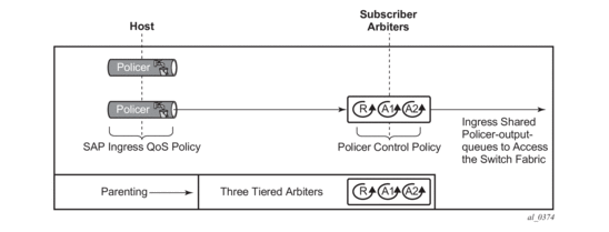
The egress hierarchical parenting relationship options are shown in Figure 79.
Figure 79: Egress Policing Hierarchy Options
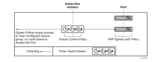
The parent command is used to specify the name of the parent arbiter when parenting a policer or arbiter, together with the level and weight at which to connect.
9.4.12.3. ATM/Ethernet Last-Mile Aware QoS for Broadband Network Gateway
This feature allows the user to perform hierarchical scheduling of subscriber host packets such that the packet encapsulation overhead and ATM bandwidth expansion (when applicable) due to the last mile for each type of broadband session, that is, PPPoEoA LLC/SNAP and VC-Mux, IPoE, IPoEoA LLC/SNAP and VC-Mux, and so on, is accounted for by the 7450 ESS and 7750 SR acting as the Broadband Network Gateway (BNG).
The intent is that the BNG distributes bandwidth among the subscriber host sessions fairly by accounting for the encapsulation overhead and bandwidth expansion of the last mile such that packets are less likely to be dropped downstream in the DSLAM DSL port.
The last mile encapsulation type can be configured by the user or signaled using the Access-loop-encapsulation sub-TLV in the Vendor-Specific PPPoE Tags or DHCP Relay Options as per RFC 4679.
Furthermore, this feature allows the BNG to shape the aggregate rate of each subscriber and the aggregate rate of all subscribers destined to a given DSLAM to prevent congestion of the DSLAM. The subscriber aggregate rate is adjusted for the last mile overhead. The shaping to the aggregate rate of all subscribers of a given destination DSLAM is achieved via a new scheduling object, referred to as Virtual Port or vport in CLI, which represents the DSLAM aggregation node in the BNG scheduling hierarchy
9.4.12.3.1. Broadband Network Gateway Application
An application of this feature in a BNG is shown in Figure 80.
Figure 80: BNG Application
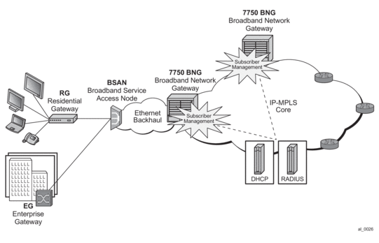
Residential and business subscribers use PPPoEoA, PPoA, IPoA, or IPoEoA based session over ATM/DSL lines. Each subscriber host can use a different type of session. Although Figure 1 illustrates ATM/DSL as the subscriber last mile, this feature supports both ATM and Ethernet in the last mile.
A subscriber SAP is auto-configured via DHCP or RADIUS authentication process, or is statically configured, and uses a Q-in-Q SAP with the inner C-VLAN identifying the subscriber while the outer S-VLAN identifies the Broadband Service Access Node (BSAN) which services the subscriber, i.e., the DSLAM. The SAP configuration is triggered by the first successfully validated subscriber host requesting a session. Within each subscriber SAP, there can be one or more hosts using any of the above session types. The subscriber SAP terminates on an IES or VPRN service on the BNG. It can also terminate on a VPLS instance.
When the 7750 BNG forwards IP packets from the IP-MPLS core network downstream towards the Residential Gateway (RG) or the Enterprise Gateway (EG), it adds the required PPP and Ethernet headers, including the SAP encapsulation with C-VLAN/S-VLAN. When the BSAN node receives the packet, it strips the S-VLAN tag, strips or overwrites the C-VLAN tag, and adds padding to minimum Ethernet size if required. It also adds the LLC/SNAP or VC-mux headers plus the fixed AAL5 trailer and variable AAL5 padding (to next multiple of 48 bytes) and then segments the resulting PDU into ATM cells when the last mile is ATM/DSL. Thus the packet size will undergo a fixed offset due to the encapsulation change and a variable expansion due to the AAL5 padding when applicable. Each type of subscriber host session will require a different amount of fixed offset and may require a per packet variable expansion depending of the encapsulation used by the session. The BNG node learns the encapsulation type of each subscriber host session by inspecting the Access-loop-encapsulation sub-TLV in the Vendor-Specific PPPoE Tags as specified in RFC 4679. The BNG node must account for this overhead when shaping packets destined to subscriber.
9.4.12.3.2. Queue Determination and Scheduling
Figure 81 illustrates the queuing and scheduling model for a BNG using the Ethernet/ATM last-mile aware QoS feature.
Figure 81: BNG Queuing and Scheduling Model
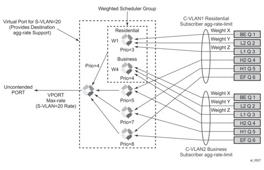
A set of per FC queues are applied to each subscriber host context to enforce the packet rate within each FC in the host session as specified in the subscriber’s host SLA profile. A packet is stored in the queue corresponding the packet’s FC as per the mapping of forwarding class to queue-id defined in the sap-egress QoS policy used by the host SLA profile. In the BNG application however, the host per FC queue packet rate is overridden by the rate provided in the RADIUS access-accept message. This rate represents the ATM rate that will be seen on the last mile, that is, it includes the encapsulation offset and the per packet expansion due to ATM segmentation into cells at the BSAN.
In order to enforce the aggregate rate of each destination BSAN, a scheduling node, referred to as virtual port, and vport is in the CLI. The vport operates exactly like a port scheduler with the difference that multiple vport objects can be configured on the egress context of an Ethernet port. The user adds a vport to an Ethernet port using the following command:
The vport is always configured at the port level even when a port is a member of a LAG. The vport name is local to the port it is applied to but must be the same for all member ports of a LAG. It however does not need to be unique globally on a chassis.
The vport is always configured at the port level even when a port is a member of a LAG. The vport name is local to the port it is applied to but must be the same for all member ports of a LAG. It however does not need to be unique globally on a chassis.
The user applies a port scheduler policy to a vport using the following command:
A vport cannot be parented to the port scheduler when it is using a port scheduler policy itself. It is thus important the user ensures that the sum of the max-rate parameter value in the port scheduler policies of all vport instances on a given egress Ethernet port does not oversubscribe the port’s hardware rate. If it does, the scheduling behavior degenerates to that of the H/W scheduler on that port. A vport which uses an agg-rate can be parented to a port scheduler. This is explained in Applying Aggregate Rate Limit to a Vport. Note that the application of the agg-rate rate, port-scheduler-policy and scheduler-policy commands under a vport are mutually exclusive.
Each subscriber host queue is port parented to the vport which corresponds to the destination BSAN using the existing port-parent command:
This command can parent the queue to either a port or to a vport. These operations are mutually exclusive in CLI as explained above. When parenting to a vport, the parent vport for a subscriber host queue is not explicitly indicated in the above command. It is determined indirectly. The determination of the parent vport for a given subscriber host queue is described in Vport Determination and Evaluation.
Furthermore, the weight (cir-weight) of a queue is normalized to the sum of the weights (cir-weights) of all active subscriber host queues port-parented at the same priority level of the vport or the port scheduler policy. Since packets of ESM subscriber host queues are sprayed among the link of a LAG port based on the subscriber-id, it is required that all subscribers host queues mapping to the same vport, such as having the same destination BSAN, be on the same LAG link so that the aggregate rate towards the BSAN is enforced. The only way of achieving this is to operate the LAG port in active/standby mode with a single active link and a single standby link.
The aggregate rate of each subscriber must also be enforced. The user achieves this by applying the existing agg-rate-limit command to the egress context of the subscriber profile:
In the BNG application however, this rate is overridden by the rate provided in the RADIUS access-accept message. This rate represents the ATM rate that will be seen on the last mile, that is, it includes the encapsulation offset and the per packet expansion due to ATM segmentation into cells at the BSAN.
9.4.12.3.3. Weighted Scheduler Group
The existing port scheduler policy defines a set of eight priority levels with no ability of grouping levels within a single priority. In order to allow for the application of a scheduling weight to groups of subscriber host queues competing at the same priority level of the port scheduler policy applied to the vport, or to the Ethernet port, a new group object is defined under the port scheduler policy:
Up to eight groups can be defined within each port scheduler policy. One or more levels can map to the same group. A group has a rate and optionally a cir-rate and inherits the highest scheduling priority of its member levels. For example, the scheduler group shown in the vport consists of level priority 3 and level priority 4. It thus inherits priority 4 when competing for bandwidth with the standalone priority levels 8, 7, and 5.
In essence, a group receives bandwidth from the port or from the vport and distributes it within the member levels of the group according to the weight of each level within the group. Each priority level will compete for bandwidth within the group based on its weight under congestion situation. If there is no congestion, a priority level can achieve up to its rate (cir-rate) worth of bandwidth.
The mapping of a level to a group is performed as follows:
| Note: CLI will enforce that mapping of levels to a group are contiguous. In other words, a user would not be able to add priority level to group unless the resulting set of priority levels is contiguous. |
When a level is not explicitly mapped to any group, it maps directly to the root of the port scheduler at its own priority like in existing behavior.
9.4.12.3.4. Queue and Subscriber Aggregate Rate Configuration and Adjustment
Software-Based Implementation (8.0R4)
The subscriber aggregate rate is adjusted and it will be based on an average frame size.
The user enables the use of this adjustment method by configuring the following option in the egress context of the subscriber profile:
This command allows the user to configure a default value to be used by all hosts of the subscriber in the absence of a valid signaled value. The following is a list of the configurable values:
Values: | pppoa-llc, pppoa-null, pppoeoa-llc, pppoeoa-llc-fcs, pppoeoa-llc-tagged, pppoeoa-llc- |
agged-fcs, pppoeoa-null, pppoeoa-null-fcs, pppoeoa-null-tagged, pppoeoa-null-tagged-fcs | |
ipoa-llc, ipoa-null, ipoeoa-llc, ipoeoa-llc-fcs, ipoeoa-llc-tagged, ipoeoa-llc-tagged-fcs, | |
poeoa-null, ipoeoa-null-fcs, ipoeoa-null-tagged, ipoeoa-null-tagged-fcs, | |
pppoe, pppoe-tagged, | |
ipoe, ipoe-tagged |
Otherwise, the fixed packet offset will be derived from the encapsulation type value signaled in the Access-loop-encapsulation sub-TLV in the Vendor-Specific PPPoE Tags as explained in Section Signaling of Last Mile Encapsulation Type. Only signaling using PPPoE Tags is supported in the software based implementation. The last signaled valid value is then applied to all active hosts of this subscriber. If no value is signaled in the subscriber host session or the value in the fields of the Access-loop-encapsulation sub-TLV are invalid, then the offset applied to the aggregate rate of this subscriber will use the last valid value signaled by a host of this subscriber if it exists, or the user entered default type value if configured, or no offset is applied.
The user also configures the average frame size value to be used for this adjustment:
The value entered by the user must include the FCS but not the Inter-Frame Gap (IFG) or the preamble. If the user does not explicitly configure a value for the avg-frame-size parameter, then it will also be assumed the offset is zero regardless of the signaled or user-configured value.
The computation of the subscriber aggregate rate consists of taking the average frame size, adding the encapsulation fixed offset including the AAL5 trailer, and then adding the variable offset consisting of the AAL5 padding to next multiple of 48 bytes. The AverageFrameExpansionRatio is then derived as follows:
AverageFrameExpansionRatio = (53/48 x (AverageFrameSize + FixedEncapOffset + AAL5Padding)) / (AverageFrameSize + IFG + Preamble).
When the last mile is Ethernet, the formula simplifies to:
AverageFrameExpansionRatio = (AverageFrameSize + FixedEncapOffset + IFG + Preamble) / (AverageFrameSize + IFG + Preamble).
The following are the frame size and rate applied to the subscriber queue and scheduler:
Subscriber Host Queue (no change):
Size = ImmediateEgressEncap + Data
Rate = ImmediateEgressEncap + Data
Subscriber Aggregate Rate Scheduler:
Size = ImmediateEgressEncap + Data
Rate = sub-agg-rate / AverageFrameExpansionRatio
Note that the CPM applies the AverageFrameExpansionRatio adjustment to the various components used in the determination of the net subscriber operational aggregate rate. It then pushes these adjusted components to IOM which then makes the calculation of the net subscriber operational aggregate rate.
The formula used by the IOM for this determination is:
sub-oper-agg-rate = min(sub-policy-agg-rate/AverageFrameExpansionRatio, ancp_rate/AverageFrameExpansionRatio) + (igmp_rate_delta/AverageFrameExpansionRatio),
where sub-policy-agg-rate is either the value configured in the agg-rate-limit parameter in the subscriber profile or the resulting RADIUS override value. In both cases, the CPM uses an internal override to download the adjusted value to IOM.
The value of sub-oper-agg-rate is stored in the IOM's subscriber table.
The following are the procedures for handling signaling changes or configuration changes affecting the subscriber profile:
- If a new RADIUS update comes in for the aggregate subscriber rate, then a new subscriber aggregate ATM adjusted rate is computed by CPM using the last configured avg-frame-size and then programmed to IOM.
- If the user changes the value of the avg-frame-size parameter, enables/disables the encap-offset option, or changes the parameter value of the encap-offset option, the CPM will immediately trigger a re-evaluation of subscribers using the corresponding subscriber profile and an update the IOM with the new subscriber aggregate rate.
- If the user changes the value of the agg-rate-limit parameter in a subscriber profile which has the avg-frame-size configured, this will immediately trigger a re-evaluation of subscribers using the corresponding subscriber profile. An update to the subscriber aggregate rate is performed for those subscribers which rate has not been previously overridden by RADIUS.
- If the user changes the type value of the encap-offset command, this will immediately trigger a re-evaluation of subscribers using the corresponding subscriber profile. An update to the subscriber aggregate rate is performed for those subscribers which are currently using the default value.
- If two hosts of the same subscriber signal two different encapsulation types, the last one signaled gets used at the next opportunity to re-evaluate the subscriber profile.
- If a subscriber has a DHCP host, a static host or an ARP host, the subscriber aggregate rate will continue to use the user-configured default encapsulation type value or the last valid encapsulation value signaled in the PPPoE tags by other hosts of the same subscriber. If none was signaled or configured, then no rate adjustment is applied.
Hardware-Based Implementation
The data path will compute the adjusted frame size real-time for each serviced packet from a queue by adding the actual packet size to the fixed offset provided by CPM for this queue and variable AAL5 padding.
Like in the software based implementation, the user enables the use of the fixed offset and per packet variable expansion by configuring the following option in the egress context of the subscriber profile:
When this command is enabled, the fixed packet offset will be derived from the encapsulation type value signaled in the Access-loop-encapsulation sub-TLV in the Vendor-Specific PPPoE Tags or DHCP Relay Options as explained in Section Signaling of Last Mile Encapsulation Type.
If the user specifies an encapsulation type with the command, this value will be used as the default value for all hosts of this subscriber until a host session signaled a valid value. The signaled value is applied to this host only and the remaining hosts of this subscriber continue to use the user entered default type value if configured, or no offset is applied. Note however that hosts of the same subscriber using the same SLA profile and which are on the same SAP will share the same instance of FC queues. In this case, the last valid encapsulation value signaled by a host of that same instance of the SAP egress QoS policy will override any previous signaled or configured value.
The procedures for handling signaling changes or configuration changes affecting the subscriber profile are the same as in the Software based implementation with except for the following:
- The avg-frame-size parameter in the subscriber profile is ignored.
- If the user specifies an encapsulation type with the command, this value will be used as the default value for all hosts of this subscriber until a host session signaled a valid value. The signaled value is applied to this host and other hosts of the same subscriber sharing the same SLA profile and which are on the same SAP. The remaining hosts of this subscriber continue to use the user entered default type value if configured, or no offset is applied.
- If the user enables/disables the encap-offset option, or changes the parameter value of the encap-offset option, the CPM will immediately trigger a re-evaluation of subscribers hosts using the corresponding subscriber profile and an update the IOM with the new fixed offset value.
- If subscriber host session signals an encapsulation type at the session establishment time and subsequently sends a DHCP renewal message using a Layer 2 DHCP relay which does not insert option82 in a unicast message, the encapsulation type for this host will not change. Note that TR-101 states that option82 is mandatory for DHCP broadcast messages).
- If a subscriber has a static host or an ARP host, the subscriber host will continue to use the user-configured default encapsulation type value or the last valid encapsulation value signaled in the PPPoE tags or DHCP relay options by other hosts of the same subscriber which use the same SLA profile instance. If none was signaled or configured, then no rate adjustment is applied.
- The encapsulation type value signaled in DHCP relay options or PPPoE tags are not cross-checked against the host type. So, a host signaling PPPoA/LLC encapsulation type via DHCP relay options will be handled as if the packet included a PPPoE header when forwarded over the local Ethernet port. This results in applying an encap-offset in the data path which assumes the PPPoE header is added to forwarded packets over the local Ethernet port.
The encap-offset option forces all the rates to be either last-mile frame over the wire or local port frame over the wire, referred to as LM-FoW and FoW respectively. The system maintains a running average frame expansion ratio for each queue to convert queue rates between these two formats as explained in Frame Size, Rates, and Running Average Frame Expansion Ratio. Here are the details of the queue and scheduler operation:
- When the encap-offset option is configured in the subscriber profile, the subscriber host queue rates, that is, CLI and operational PIR and CIR as well as queue bucket updates, the queue statistics, that is, forwarded, dropped, and HQoS offered counters use the LM-FoW format. The scheduler policy CLI and operational rates also use LM-FoW format. The port scheduler max-rate and the priority level rates and weights, if a Weighted Scheduler Group is used, are always entered in CLI and interpreted as FoW rates. The same is true for an agg-rate-limit applied to a vport. Finally the subscriber agg-rate-limit is entered in CLI as LM-FoW rate. When converting between LM-FoW and FoW rates, the queue running average frame expansion ratio value is used.
- If the user enabled frame-based-accounting in a scheduler policy or queue-frame-based-accounting with subscriber agg-rate-limit and a port scheduler policy, the queue operational rate will be capped to a user configured FoW rate. The scheduler policy operational rates will also be in the FoW format. Note that a user configured queue avg-frame-overhead value is ignored since the running average frame expansion ratio is what is used when the encap-offset option is enabled.
- If the user configured queue packet-byte-offset value, it is ignored and is not accounted for in the net packet offset calculation.
- When no encap-offset is configured in the subscriber profile, that is, default and pre-R9.0 behavior, queue CLI and operational PIR and CIR rates, as well as queue bucket updates, the queue statistics, use data format. The scheduler policy CLI and operational rates also use data format. The port scheduler max-rate and the priority level rates and weights, if a Weighted Scheduler Group is used, and the subscriber agg-rate-limit are entered in CLI and interpreted as FoW rates. When converting between FoW and data rates, the queue avg-frame-overhead value is used and since this an Ethernet port, it is not user-configurable but constant and is equal to +20 bytes (IFG and preamble).
- If the user enabled frame-based-accounting in a scheduler policy or queue-frame-based-accounting with subscriber agg-rate-limit and a port scheduler policy, the queue operational rate will be capped to a user configured FoW rate in CLI which is then converted into a data rate using the queue avg-frame-overhead constant value of +20 bytes. The scheduler policy operational rates will also be in the FoW format.
- If the user configured queue packet-byte-offset value, it adjusts the immediate packet size. This means that the queue rates, that is, operational PIR and CIR, and queue bucket updates use the adjusted packet size. In addition, the queue statistics will also reflect the adjusted packet size. Scheduler policy rates, which are data rates, will use the adjusted packet size. The port scheduler max-rate and the priority level rates and weights, if a Weighted Scheduler Group is used, as well as the subscriber agg-rate-limit are always FoW rates and thus use the actual frame size. Packet byte offset settings are not included in the applied rate when (queue) frame based accounting is configured, however, the offsets are applied to the statistics.
9.4.12.3.5. Frame Size, Rates, and Running Average Frame Expansion Ratio
The following are the details of the rates and frame sizes applied to the subscriber host queues, the subscriber aggregate rate, and the vport root scheduler for the scheduling model and when the encap-offset option is enabled in the subscriber profile.
Subscriber Host Queue:
Size = LastMileFrameOverWireEncap + Data
Rate = (48/53)* x (LastMileFrameOverWireEncap + Data)
*Applicable to ATM last-mile only.
Subscriber Aggregate Rate:
Size = LastMileFrameOverWireEncap + Data
Rate = (48/53)* x (LastMileFrameOverWireEncap + Data)
*Applicable to ATM last-mile only.
Vport/Port Port Scheduler and Weighted Scheduler Group
Size = FrameOverWireEncap + Data
Rate = FrameOverWireEncap + Data
When a frame arrives at the queue, it size will be ImmediateEgressEncap+Data. This size is stored as the OfferedFrameSize so that the queue offered stats used in HQoS calculations are correct. Let us refer to the HQoS offered statistics as Offered.
This size is then adjusted by removing the ImmediateEgressEncap and adding the LastMileFrameOverWireEncap. This new adjusted frame size, let us refer to it as LastMileOfferedFrameSize, is then used for checking compliance of the frame against the queue PIR and CIR bucket sizes and for updating the queue forwarded and dropped stats.
The LastMileOfferedFrameSize value is computed dynamically for each packet serviced by the queue.
A new HQoS stat counter OfferedLastMileAdjusted is maintained for the purpose of calculating the running average frame expansion ratio, which is the ratio of the accumulated OfferedLastMileAdjusted and Offered of each queue:
RunningAverageFrameExpansionRatio = OfferedLastMileAdjusted / Offered
The vport/port port scheduler will hand out its FoW bandwidth in terms of Fair Information Rate (FIR) bandwidth to each subscriber queue. This queue FIR must be converted into LM-FoW format to cap it by the queue PIR (adminPIR) and to make sure the sum of FIRs of all queues of the same subscriber does not exceed the subscriber agg-rate-limit which is also expressed in LM-FoW format. The conversion between these two rates makes use of the cumulative RunningAverageFrameExpansionRatio value.
Note that a queue LM-foW AdminPIR value will always be capped to the value of the local port FoW rate even if the conversion based on the current RunningAverageFrameExpansionRatio value indicates that a higher AdminPIR may be able to fill in the full line rate of the local port.
9.4.12.3.6. Vport Determination and Evaluation
In the BNG application, host queues of all subscribers destined to the same downstream BSAN, for example, all SAPs on the egress port matching the same S-VLAN tag value, are parented to the same vport which matches the destination ID of the BSAN.
The BNG determines the parent vport of a subscriber host queue, which has the port-parent option enabled, by matching the destination string dest string associated with the subscriber with the string defined under a vport on the port associated with the subscriber.
The user configures the dest string match under the egress context of the Ethernet port associated with the subscriber:
If a given subscriber host queue does not have the port-parent option enabled, it will be foster-parented to the vport used by this subscriber and which is based on matching the dest string. If the subscriber could not be matched with a vport on the egress port, the host queue will not be bandwidth controlled and will compete for bandwidth directly based on its own PIR and CIR parameters.
By default, a subscriber host queue with the port-parent option enabled is scheduled within the context of the port’s port scheduler policy. In order to indicate the option to schedule the queue in the context of a port scheduler policy associated with a vport, the user enters the following command in SLA profile used by the subscriber host:
This command is persistent meaning that the user can re-enter the qos node without specifying the vport-scheduler argument each time and the system will remember it. The user can revert to the default setting without deleting the association of the SLA profile with the SAP egress QoS policy by explicitly re-entering the command with the following new argument:
9.4.12.3.7. Applying Aggregate Rate Limit to a Vport
The user can apply an aggregate rate limit to the vport and apply a port scheduler policy to the port.
This model allows the user to oversubscribe the Ethernet port. The application of the agg-rate option is mutually exclusive with the application of a port scheduler policy, or a scheduler policy to a vport.
When using this model, a subscriber host queue with the port-parent option enabled is scheduled within the context of the port’s port scheduler policy. However, the user must still indicate to the system that the queues are managed by the aggregate rate limit instance of a vport by enabling the vport-scheduler option in the subscriber host SLA profile:
A subscriber host-queue which is port-parented will be parented to the port scheduler policy of the port used by the subscriber and aggregate rate limited within the instance of the vport used by this subscriber and which is based on matching the dest string and org string. If the vport exists but the port does not have a port scheduler policy applied, then the host queue will be orphaned and no aggregate rate limit can be enforced.
If a given subscriber host queue does not have the port-parent option enabled, it will be foster-parented to the port used by this subscriber and aggregate rate limited within the instance of the vport used by this subscriber. If the vport exists but the port does not have a port scheduler policy applied, then the host queue will be orphaned and no aggregate rate limit can be enforced.
9.4.12.3.8. Applying a Scheduler Policy to a Vport
The user can apply a scheduler policy to the vport. This is allows scheduling control of subscriber tier 1 schedulers in a scheduler policy applied to the egress of a subscriber or SLA profile, or to a PW SAP in an IES or VPRN service.
The advantage of using a scheduler policy under a vport, compared to the use of a port scheduler (with or without an agg-rate rate), is that it allows a port parent to be configured at the vport level.
Bandwidth distribution from an egress port scheduler to a vport configured with a scheduler policy can be performed based on the level/cir-level and weight/cir-weight configured under the scheduler’s port parent. The result is in allowing multiple vports, for example representing different DSLAMs, to share the port bandwidth capacity in a flexible way that is under the control of the user.
The configuration of a scheduler policy under a vport is mutually exclusive with the configuration of a port scheduler policy or an aggregate rate limit.
A scheduler policy is configured under a vport as follows:
When using this model, a tier 1 scheduler in a scheduling policy applied to a subscriber profile or SLA profiles must be configured as follows:
If the vport exists, but port does not have a scheduler policy applied, then its schedulers will be orphaned and no port level QOS control can be enforced.
The following show/monitor/clear commands are available related to the vport scheduler:
HQoS adjustment and host tracking are not supported on schedulers that are configured in a scheduler policy on a vport, so the configuration of a scheduler policy under a vport is mutually exclusive with the configuration of the egress-rate-modify parameter.
ESM over MPLS pseudowires are not supported when a scheduler policy is configured on a vport.
9.4.12.3.9. Signaling of Last Mile Encapsulation Type
A subscriber host session can signal one of many encapsulation types each with a different fixed offset in the last mile. These encapsulation types are described in RFC 4679 and are illustrated in Figure 82 and Figure 83. The BNG node learns the encapsulation type of each subscriber host session by inspecting the Access-loop-encapsulation sub-TLV in the Vendor-Specific PPPoE Tags as specified in RFC 4679.When Ethernet is the last mile, the encapsulation type will result in a fixed offset for all packet sizes. When ATM/DSL is the last mile, there will be an additional expansion due to AAL5 padding to next multiple of 48 bytes and which varies depending on the packet size.
Both ATM and Ethernet access using PPP encapsulation options are supported in the software and hardware based implementations. Thus both provide support for the Access-loop-encapsulation sub-TLV in the Vendor-Specific PPPoEv4/PPPoEv6 Tags with the ATM encapsulation values and Ethernet encapsulation values.
ATM and Ethernet access using IP encapsulation are only supported using default encapsulation offset configuration in the subscriber profile in the software based implementation. Support for signaling the Access-loop-encapsulation sub-TLV in the DHCPv4/DHCPv6 Relay Options is included in the hardware based implementation. There is no support for DHCPv6 relay options.
Figure 82: Subscriber Host Session Encapsulation Types
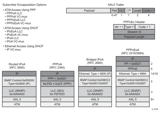
Figure 83: Access-Loop-Encapsulation Sub-TLV
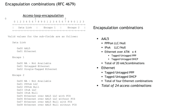
The operational last-mile values for hosts on the same sap, having the same SLA profile are displayed in following the show-command:
The data-link can have values: atm, other and unknown. If no offset is supplied it will be set to unknown. Other is used when the data-link is non-atm, otherwise it will state atm.
Operational per-queue values can also be found in the show-command:
Here, one can see whether the queue is operating in last-mile mode. Note that this command is not available on HSMDAv2,
Last Mile ATM
Last Mile Ethernet
Next Mile ATM
9.4.12.3.10. Configuration Example
The following CLI configuration achieves the specific use case shown in Figure 81.
9.4.13. Subscriber Volume Statistics
Subscriber volume statistics or octet and packet counters are available through the queues and policers that are instantiated for the subscriber. The queue and policer configuration is defined in the SLA profile via ingress and egress qos policy associations with optional overrides. Subscriber hosts that belong to the same subscriber, that are active on the same SAP and that have the same sla-profile will share the set of queues and policers defined by that SLA profile instance. For HSMDA hardware, the ingress policer/queue and egress queue configuration is defined in the subscriber profile via ingress and egress qos policy associations with optional overrides. All hosts belonging to the subscriber share the same set of queues and policers.
9.4.13.1. IP (Layer 3) Volume Accounting
Subscriber volume statistics by default count Layer 2 frame sizes optionally modified by configuration such as packet-byte-offset, last mile aware shaping, etc.
To report subscriber volume statistics as Layer 3 (IP) packet sizes, the volume-stats-type can be configured to ip in the subscriber profile:
volume-stats-type ip affects the subscriber statistics in SNMP, CLI, RADIUS accounting, XML accounting and Diameter Gx usage monitoring. Volume quota for RADIUS or Diameter Credit Control applications are interpreted as Layer 3 quota.
The following restrictions apply for volume-stats-type ip:
- Layer-3/IP accounting is not supported in combination with last-mile-aware shaping on HSMDA
- Layer-3/IP accounting is not supported in combination with ESMoPW on HSMDA
- Layer-3/IP accounting is not supported in combination with MLPPP
- Layer-3/IP accounting in combination with ESMoPW and last-mile-aware shaping may be inaccurate if the MPLS encapsulation overhead changes during the lifetime of a subscriber.
- Layer-3/IP accounting is restricted to a single encap per sla-profile instance (queue instance). The first host associated with the sla-profile instance (queue instance) determines the allowed encap. Conflicting encaps are:
- PPPoE and IPoE on regular Ethernet SAPs
- PPPoE and IPoE on PW SAPs
- PPPoA and PPPoEoA on ATM ports
- PPPoE keep alive packets do not contain IP payload and introduce an error in Layer-3/IP accounting when enabled in combination with L2TP-LAC. A workaround is to isolate the keep alives in a separate queue/policer.
- Padding of frames smaller than the Ethernet minimum frame size (64B) may introduce an inaccuracy in Layer-3/IP accounting.
- With ATM in the last mile, last-mile-aware shaping may introduce an inaccuracy in Layer-3/IP accounting.
- Packet-Byte-Offset (PBO) changes during the lifetime of a subscriber introduces an inaccuracy in Layer-3/IP accounting.
9.4.13.2. Separate IPv4 and IPv6 Counters
IPv4 and IPv6 forwarded and dropped subscriber traffic can be counted separately via a stat-mode v4-v6 command that is configured as a policer or queue qos override in the sla-profile. The stat-mode v4-v6 command is only applicable for Enhanced Subscriber Management (ESM).
For policers, the stat-mode command overrides the policer stat-mode configuration as defined in the sap-ingress or sap-egress qos policy. For details on sap-ingress and sap-egress policer stat-mode, refer to the Quality of Service Guide. For a policer in stat-mode v4-v6, following counters are available:
- Offered IPv4 octets and packets
- Offered IPv6 octets and packets
- Dropped IPv4 octets and packets
- Dropped IPv6 octets and packets
- Forwarded IPv4 octets and packets
- Forwarded IPv6 octets and packets
When a policer’s stat-mode is changed while the sla profile is in use, any previous counter values are lost and any new counters are set to zero.
For queues, a stat-mode is only available for use in Enhanced Subscriber Management (ESM) context to enable separate IPv4/IPv6 counters. For a queue in stat-mode v4-v6, following counters are available:
- Offered High Priority, Low Priority, Uncolored, Managed octets and packets
- Dropped IPv4 octets and packets
- Dropped IPv6 octets and packets
- Forwarded IPv4 octets and packets
- Forwarded IPv6 octets and packets
A queue’s stat-mode cannot be changed while the sla profile is in use.
Note that there will be no in-profile/out-of-profile forwarded and dropped counters for policers and queues in stat-mode v4-v6.
Non IP traffic (for example PPPoE LCP frames) is counted against the IPv4 counters.
The separate IPv4 and IPv6 forwarded and dropped counters are reported in
- SNMP
- CLI
- RADIUS accounting
When a queue or policer is configured in stat-mode v4-v6, existing VSA’s are re-used in RADIUS detailed per queue / per policer accounting (configure subscriber-mgmt radius-accounting-policy <name> include-radius-attribute detailed-acct-attributes):
- in-profile counter VSA’s map to IPv4 octets/packets
- ingress queue high priority dropped counter VSA’s map to IPv4 octets/packets
- out-of-profile counter VSA’s map to IPv6 octets/packets
- ingress queue low priority dropped counter VSA’s map to IPv6 octets/packets
In addition the [26-6527-107] Alc-Acct-I-statmode / [26-6527-127] Alc-Acct-O-statmode is sent with value set to “v4-v6”.
Optionally a set of VSA's can be included in RADIUS accounting to report the aggregate IPv6 forwarded octets and packets of queues and policers with stat-mode v4-v6 enabled (configure subscriber-mgmt radius-accounting-policy <name> include-radius-attribute detailed-acct-attributes v6-aggregate-stats):
[26-6527-194] Alc-IPv6-Acct-Input-Packets
[26-6527-195] Alc-IPv6-Acct-Input-Octets
[26-6527-196] Alc-IPv6-Acct-Input-GigaWords
[26-6527-197] Alc-IPv6-Acct-Output-Packets
[26-6527-198] Alc-IPv6-Acct-Output-Octets
[26-6527-199] Alc-IPv6-Acct-Output-Gigawords
Refer to the 7750 SR RADIUS Attributes Reference Guide for a detailed description of all counter attributes.
- XML accounting
The complete-subscriber-ingress-egress and custom-record-subscriber XML records use following fields to represent IPv4 and IPv6 forwarded/dropped octets and packets for queues or policers with stat-mode v4-v6 enabled:
v4po - IPv4PktsOffered (policer only)
v4oo - IPv4OctetsOffered (policer only)
v6po - IPv6PktsOffered (policer only)
v6oo - IPv6OctetsOffered (policer only)
v4pf - IPv4PktsForwarded
v6pf - IPv6PktsForwarded
v4pd - IPv4PktsDropped
v6pd - IPv4PktsDropped
v4of - IPv4OctetsForwarded
v6of - IPv6OctetsForwarded
v4od - IPv4OctetsDropped
v6od - IPv4OctetsDropped
For custom records, the following CLI is re-used to include v4/v6 counters if the queue is configured in stat-mode v4-v6:
i-counters
all-packets-offered-count # n/a
all-octets-offered-count # n/a
high-packets-offered-count # n/a
low-packets-offered-count # n/a
uncoloured-packets-offered-count # n/a
high-octets-offered-count # n/a
low-octets-offered-count # n/a
uncoloured-octets-offered-count # n/a
all-packets-offered-count # n/a
all-octets-offered-count # n/a
high-packets-discarded-count # IPv4
low-packets-discarded-count # IPv6
high-octets-discarded-count # IPv4
low-octets-discarded-count # IPv6
in-profile-packets-forwarded-count # IPv4
out-profile-packets-forwarded-count # IPv6
in-profile-octets-forwarded-count # IPv4
out-profile-octets-forwarded-count # IPv6
e-counters
in-profile-packets-forwarded-count # IPv4
in-profile-packets-discarded-count # IPv4
out-profile-packets-forwarded-count # IPv6
out-profile-packets-discarded-count # IPv6
in-profile-octets-forwarded-count # IPv4
in-profile-octets-discarded-count # IPv4
out-profile-octets-forwarded-count # IPv6
out-profile-octets-discarded-count # IPv6
On HSMDA, stat-mode v4-v6 is configured as a policer or queue qos override in the subscriber profile:
The stat-mode on egress hsmda queues is always enabled per subscriber: when enabling stat-mode v4-v6 for one hsmda queue, it is automatically enabled for all hsmda queues for that subscriber profile.
9.4.14. Configuring IP and IPv6 Filter Policies for Subscriber Hosts
Access Control Lists (ACLs) for subscriber traffic are defined as IP and IPv6 filter policies and are configured in the SLA-profile associated with the subscriber. For information about IP and IPv6 filter policy configurations, refer to the Router Configuration Guide.
Traffic from different hosts of a single subscriber and associated with the same sla-profile instance, is subject to the filter policies defined in the SLA profile.
The IP or IPv6 filter policy configuration of subscriber hosts can be dynamically updated using different mechanisms:
- Assign a new SLA profile.This can be done dynamically by, for example, a RADIUS CoA message. As the SLA profile also defines the QoS configuration for the subscriber hosts, this change may result in a discontinuity in accounting.Note: changing the ip-filter policy in an SLA profile in use by an active subscriber is allowed in the CLI, but not recommended. Changing the IPv6 filter policy in an SLA profile in use by an active subscriber is prevented in the CLI.
- Override the IP and IPv6 filter policiesAlternatively, it is also possible to dynamically override the IP and IPv6 filter policies per subscriber-host through a RADIUS Access-Accept or CoA message. Following VSA should be included in the RADIUS message:
- Insert subscriber host specific filter entriesA subscriber host specific entry is dynamically created from a RADIUS access accept or CoA message using the NAS-Filter-Rule or Alc-Ascend-Data-Filter-Host-Spec attribute (see also IP Filter Attribute Format Details for a detailed description of the attribute format):
Table 57: NAS-Filter-Rule or Alc-Ascend-Data-Filter-Host-Spec Attributes
Attribute ID
Attribute Name
Type
Limits
SR OS Format
92
NAS-Filter-Rule
String
max. 10 attributes per message or max. 10 filter entries per message
The format of a NAS-Filter-Rule is defined in rfc-3588 section-4.3. A single filter rule is a string of format “<action> <direction> <protocol> from <source> to <destination> <options>”. Multiple rules should be separated by a NUL (0x00). A NAS-Filter-Rule attribute may contain a partial rule, one rule, or more than one rule. Filter rules may be continued across attribute boundaries.
A RADIUS message with NAS-Filter-Rule attribute value equal to 0x00 or “ “ (a space) removes all host specific filter entries for that host.
See also IP Filter Attribute Format Details.
For example:
Nas-Filter-Rule = "permit in ip from any to 10.1.1.1/32"
26-6527-159
Alc-Ascend-Data-Filter-Host-Spec
octets
max. 10 attributes per message or max. 10 filter entries per message.
min. length 22 bytes (IPv4), 46 bytes (IPv6)
max. length: 110 bytes (IPv4), 140 bytes (IPv6)
a string of octets with fixed field length (type (ipv4/ipv6), direction (ingress/egress), src-ip, dst-ip, ...). Each attribute represents a single filter entry. See IP Filter Attribute Format Details for a description of the format.
For example:
# "permit in ip from any to 10.1.1.1/32"
Alc-Ascend-Data-Filter-Host-Spec = 0x01010100000000000a01010100200000000000000000
The Alc-Subscriber-Filter VSA is a comma separated list of strings:
Table 58: Alc-Subscriber-Filter VSA Fields
Field | Use |
Ingr-v4:<number> | Ingress ipv4 filter |
Egr-v4:<number> | Egress ipv4 filter |
Ingr-v6:<number> | Ingress ipv6 filter |
Egr-v6:<number> | Egress ipv6 filter |
The filter number can have following values:
Table 59: Filter Number Results
<number> | Result |
1..65535 | Ignore filter from sla-profile configuration and assign corresponding pre-configured filter |
0 | Ignore filter from sla-profile configuration and do not assign a new filter (only allowed if no dynamic subscriber host specific rules are present) |
-1 | No change in filter configuration |
-2 | Restore filter from sla-profile configuration |
Notes:
- Not relevant fields (IPv4 filters for an IPv6 host) will be ignored.
- RADIUS CoA message: if the ingress or egress field is missing in the VSA, there will be no change for that direction.
- RADIUS Access-Accept message: if the ingress or egress field is missing in the VSA, then the IP filters as specified in the SLA profile will be active for that direction.
An SLA profile IP filter override is applicable to all dynamic host types, including L2TP LNS but excluding L2TP LAC.
- Insert subscriber host specific filter entriesA subscriber host specific entry is a filter entry where the match criteria is automatically extended with the subscriber host IP or IPv6 address as source (ingress) or destination (egress) IP. They represent a per host customization of a generic filter policy: only traffic to/from the subscriber host will match against these entries.A subscriber host specific entry is dynamically created from a RADIUS access accept or CoA message using the NAS-Filter-Rule attribute:
The format used to specify host specific filter entries (NAS-Filter-Rule format or Alc-Ascend-Data-Filter-Host-Spec format) cannot change during the lifetime of the subscriber host. A RADIUS message can only contain a single format for host specific filter entries.
Up to 10 host specific filter rules can be specified in a single RADIUS message. Each new RADIUS CoA message containing host specific filter attributes overwrites the previous subscriber host-specific filter entries for that host provided that there are enough free entries in the reserved range.
Subscriber host specific filter entries can be removed with a RADIUS CoA message with NAS-Filter-Rule attribute value equal to 0x00 or “ “ (a space).
When the subscriber host session terminates or is disconnected the corresponding subscriber host specific filter entries are also deleted.
Note that subscriber host-specific filter entries are moved if the subscriber host filter policy is changed (new SLA profile or ip filter policy override) and the new filter policy contains enough free reserved entries (sub-insert-RADIUS).
A range of entries must be reserved for subscriber host specific entries in a filter policy:
High and low watermarks can be configured to raise an event when the thresholds of free entries in the reserved range are reached:
<low-watermark> : [0..100]
<high-watermark> : [0..100]
Use following show commands to check filter policy details and the filter configuration for a subscriber host:
- Insert shared filter entriesThe target application for RADIUS shared filter entries is operators that have a predefined limited number of different filter lists that each are shared with multiple subscriber hosts and that are to be managed and activated from RADIUS at authentication.A local configured ip or ipv6 filter associated with a host (sla-profile or host filter override) can be enhanced with dynamic filter entries that can be shared with multiple subscriber hosts. The shared dynamic filter entries are inserted with a set of RADIUS attributes "[242] Ascend-Data-Filter" or "[26-6527-158] Alc-Nas-Filter-Rule-Shared" received in a RADIUS Access-Accept or CoA message. A CoA message containing a set of one of those attributes overrides the previous set of shared filter entries active for that subscriber host.For each unique set of dynamic filter entries received per type (ipv4/ipv6) and direction (ingress/egress), a copy is made of the local filter with the dynamic entries included at a preconfigured insert point. If the same set of dynamic filter entries is sent to subscriber hosts that have the same associated local filter, then they will share the same filter copy. When there are no more subscriber hosts associated with a filter copy, then the filter copy is deleted. A filter copy is identified as local filter id:number. For example: show filter ip 10:2Shared filter entries are moved if the subscriber host filter policy is changed (new SLA profile or ip filter policy override) and if the new filter policy contains enough free reserved entries.
Figure 84: Insert Shared Filters
A range of entries must be reserved for shared entries in a filter policy:
High and low watermarks can be configured to raise an event when the thresholds of dynamic filter copies are reached:
The format used to specify shared filter entries (Alc-Nas-Filter-Rule-Shared format or Ascend-Data-Filter format) cannot change during the lifetime of the subscriber host. A RADIUS message can only contain a single format for shared filter entries.
Shared filter entries can be removed with a RADIUS CoA message with Alc-Nas-Filter-Rule-Shared attribute value equal to 0x00 or “ “ (a space).
Table 60: Alc-Nas-Filter-Rule-Shared Attributes
Attribute ID | Attribute Name | Type | Limits | SR OS Format |
242 | Ascend-Data-Filter | Octets | multiple attributes per RADIUS message allowed. min. length 22 bytes (IPv4), 46 bytes (IPv6) max. length: 110 bytes (IPv4), 140 bytes (IPv6) | a string of octets with fixed field length (type (ipv4/ipv6), direction (ingress/egress), src-ip, dst-ip, ...). Each attribute represents a single filter entry. See IP Filter Attribute Format Details for a description of the format. For example: # "permit in ip from any to 10.1.1.1/32" Ascend-Data-Filter = 0x01010100000000000a01010100200000000000000000 |
26-6527-158 | Alc-Nas-Filter-Rule-Shared | string | Multiple attributes per RADIUS message allowed. | The format is identical to [92] NAS-Filter-Rule and is defined in rfc-3588 section-4.3. A single filter rule is a string of format “<action> <direction> <protocol> from <source> to <destination> <options>”. Multiple rules should be separated by a NUL (0x00). An Alc-Nas-Filter-Rule-Shared attribute may contain a partial rule, one rule, or more than one rule. Filter rules may be continued across attribute boundaries. A RADIUS message with Alc-Nas-Filter-Rule-Shared attribute value equal to 0x00 or “ “ (a space) removes the shared filter entries for that host. See also IP Filter Attribute Format Details. For example: Alc-Nas-Filter-Rule-Shared = "permit in ip from any to 10.1.1.1/32" |
9.4.14.1. IP Filter Attribute Format Details
The format for [92] Nas-Filter-Rule and [26-6527-158] Alc-Nas-Filter-Rule-Shared is a string formatted as: “action direction protocol from source to destination options”. Refer to the table below for details on the respective fields.
Table 61: Nas-Filter-Rule and Alc-Nas-Filter-Rule-Shared Fields
Action or Classifier | Value | Corresponding SR-OS Filter Function | |
<direction> | in | ingress | |
out | egress | ||
<protocol> | ip | — | |
any number [0..255] | — | ||
ip | — | ||
any number [1..42] | — | ||
any number [45..49] | — | ||
any number [52..59] | — | ||
any number [61..255] | — | ||
any number 43|44|50|51|60 | — | ||
from <source> | any | 100 | ingress: src-ip = host-ip-address; src-port eq 100 egress: src-ip = 0.0.0.0/0 | ::/0; src-port eq 100 |
200-65535 | ingress: src-ip = host-ip-address; src-port range 200 65535 egress: src-ip = 0.0.0.0/0 | ::/0; src-port range 200 65535 | ||
ip-prefix/length | 100 | ingress: src-ip = host-ip-address; src-port eq 100 egress: src-ip = ip-prefix/length; src-port eq 100 | |
200-65535 | ingress: src-ip = host-ip-address; src-port range 200 65535 egress: src-ip = ip-prefix/length; src-port range 200 65535 | ||
any | 100 | ingress: dst-ip = 0.0.0.0/0 | ::/0; dst-port eq 100 egress: dst-ip = host-ip-address; dst-port eq 100 | |
200-65535 | ingress: dst-ip = 0.0.0.0/0 | ::/0; dst-port range 200 65535 egress: dst-ip = host-ip-address; dst-port range 200 65535 | ||
ip-prefix/length | 100 | ingress: dst-ip = ip-prefix/length; dst-port eq 100 egress: dst-ip = host-ip-address; dst-port eq 100 | |
200-65535 | ingress: dst-ip = ip-prefix/length; dst-port range 200 65535 egress: dst-ip = host-ip-address; dst-port range 200 65535 | ||
<options: frag> | frag | fragment true (ipv4 only) | |
<options: ipoptions> | ssrr | ip-option 9 / ip-mask 255 | |
lsrr | ip-option 3/ ip-mask 255 | ||
rr | ip-option 7/ ip-mask 255 | ||
ts | ip-option 4/ ip-mask 255 | ||
!ssrr | not supported | ||
!lsrr | not supported | ||
!rr | not supported | ||
!ts | not supported | ||
ssrr,lsrr,rr,ts | not supported | ||
<options: tcpoptions> | mss | not supported | |
window | not supported | ||
sack | not supported | ||
ts | not supported | ||
!mss | not supported | ||
!window | not supported | ||
!sack | not supported | ||
!ts | not supported | ||
mss,window,sack,ts | not supported | ||
<options: established> | established | not supported | |
not supported | |||
not supported | |||
<options: setup> | setup | tcp-syn true | |
tcp-ack false | |||
protocol tcp | |||
<options: tcpflags> | syn | tcp-syn true | |
!syn | tcp-syn false | ||
ack | tcp-ack true | ||
!ack | tcp-ack false | ||
fin | not supported | ||
rst | not supported | ||
psh | not supported | ||
urg | not supported | ||
<options: icmptypesv4> | echo reply | protocol 1 / icmp-type 0 | |
destination unreachable | protocol 1 / icmp-type 3 | ||
source quench | protocol 1 / icmp-type 4 | ||
redirect | protocol 1 / icmp-type 5 | ||
echo request | protocol 1 / icmp-type 8 | ||
router advertisement | protocol 1 / icmp-type 9 | ||
router solicitation | protocol 1 / icmp-type 10 | ||
time-to-live exceeded | protocol 1 / icmp-type 11 | ||
IP header bad | protocol 1 / icmp-type 12 | ||
timestamp request | protocol 1 / icmp-type 13 | ||
timestamp reply | protocol 1 / icmp-type 14 | ||
information request | protocol 1 / icmp-type 15 | ||
information reply | protocol 1 / icmp-type 16 | ||
address mask request | protocol 1 / icmp-type 17 | ||
address mask reply | protocol 1 / icmp-type 18 | ||
- | protocol 1 / icmp-type [0..255] | ||
3-9 ( range) | not supported | ||
3,5,8,9 ( comma separated) | not supported | ||
<options: icmptypesv6> | destination unreachable | icmp-type 1 | |
time-to-live exceeded | icmp-type 3 | ||
IP header bad | icmp-type 4 | ||
echo request | icmp-type 128 | ||
echo reply | icmp-type129 | ||
router solicitation | icmp-type 133 | ||
router advertisement | icmp-type 134 | ||
redirect | icmp-type 137 | ||
The format for [242] Ascend-Data-Filter and [26-6527-159] Alc-Ascend-Data-Filter-Host-Spec is an octet string with fixed length fields. Refer to the table below for details on the respective fields.
Table 62: Ascend-Data-Filter and Alc-Ascend-Data-Filter-Host-Spec Fields
Field | Length | Value |
Type | byte | 1 = IPv4 |
3 = IPv6 | ||
Filter or forward | 1 byte | 0 = drop |
1 = accept | ||
Indirection | 1 byte | 0 = egress |
1 = ingress | ||
Spare | 1 byte | ignored |
Source IP address | IPv4 = 4 bytes | IP address of the source interface |
IPv6 = 16 bytes | ||
Destination IP address | IPv4 = 4 bytes | IP address of the destination interface |
IPv6 = 16 bytes | ||
Source IP prefix | 1 byte | Number of bits in the network portion |
Destination IP prefix | 1 byte | Number of bits in the network portion |
Protocol | 1 byte | Protocol number. Note: match the inner most header only for IPv6 |
Established | 1 byte | ignored (not implemented) |
Source port | 2 bytes | Port number of the source port |
Destination port | 2 bytes | Port number of the destination port |
Source port qualifier | 1 byte | 0 = no compare |
1 = less than | ||
2 = equal to | ||
3 = greater than | ||
4 = not equal to (not supported) | ||
destination port qualifier | 1 byte | 0 = no compare |
1 = less than | ||
2 = equal to | ||
3 = greater than | ||
4 = not equal to (not supported) | ||
Reserved | 2 bytes | ignored |
9.4.14.2. Checking Filter Policy Details
Use following show commands to check filter policy details and the filter configuration for a subscriber host:
9.4.15. ESM PPPoA/PPPoEoA
The main goal of PPP in the subscriber context is to provide authentication, to negotiate link layer parameters (such as MTU) and to negotiate IP parameters (IP address, WINS, DNS, Default Gateway, etc.).
Each PPP session is carried over a single ATM VC over to the BNG. In PPPoA environment, PPP session is directly encapsulated over ATM transport on a DSL Customer Premise Equipment (CPE).
In the PPPoEoA environment, an additional layer is added to accommodate Ethernet medium. In this fashion, a PPP session can be directly terminated on any host within the customer Ethernet network and then transported over an ATM network to the BNG. Multiple PPPoE sessions can be carried over a single ATM PVC.
However, the majority of current implementations in ATM transport networks have PPPoE session terminated at the DSL CPE and not on a host within the customer network. This PPPoE session is then transported over ATM to the BNG. Although it seems unnecessary to add the overhead associated with Ethernet on an ATM-equipped DSL CPE, mainly for historical reasons PPPoE became ingrained in the home network and as such has moved into DSL CPE.
9.4.15.1. PPPoA
In a PPPoA environment, services are offered to residential and business customers. DSL CPE and BNG are the originating and terminating points of a PPP connection. In a residential example, a DSL CPE is a Home Gateway (HG) as shown in Figure 85.
Figure 85: PPPoA Architecture and Packet Encapsulation
An ATM VC must exist between a CPE and a BNG before a PPP session can be established. From a QoS perspective, this VC is one of the following service categories: CBR, rt-VBR, nrt-VBR or UBR(+). CPE starts negotiating PPP link/session parameters over the VC. Once the IP address is obtained from the Service Provider (SP) side, the customer is ready for data transfer. There is a 1:1 mapping between a PPPoA session and a VC.
There is no need for the customer to run PPP within its own network. CPE, as a default gateway, accepts Ethernet IP packets, strips off the Ethernet header, performs a NAT function, and encapsulates the IP packets into PPPoA before it sends them on to the BNG.
In most residential cases, this PPPoA session is used for pure data transport (Internet access). As such, the BNG side would require a single service queue per VC.
In certain cases, customers use PPPoA for VoIP. In this case, they use an IAD (Integrated Access Device) to gain access to the ATM network.
It must be noted here that nothing in this architecture precludes customers from using multiple services over a single PPPoA session. Services would be differentiated through DSCP bits and each service in this case would require a separate queue. This is most likely a scenario with business customers where a customer runs multiple services over a PPPoA session. DSL CPE would play a role here in differentiating and appropriately marking the services, either through a separate physical port per service or through some other means.
9.4.15.2. PPPoEoA
In the PPPoE model the originating PPP point could extends beyond the DSL CPE and into the customer Ethernet network where any host can originate a PPP session. In such case, ATM is generally used as a transport to carry PPPoE sessions that are originated by hosts within the customer network (beyond DSL CPE). The DSL CPE would operate in a bridged mode. This is shown in Figure 86.
Figure 86: PPoEoA Host Terminated Session
However, the majority of deployments have PPPoE sessions terminated in DSL CPE. Although it is inefficient to add an extra Ethernet encapsulation layer over ATM-equipped DSL CPE, the evolution of PPP in broadband is the chief reason for this deployment scenario as shown in Figure 87.
Figure 87: PPPoEoA DSL CPE Terminated Session
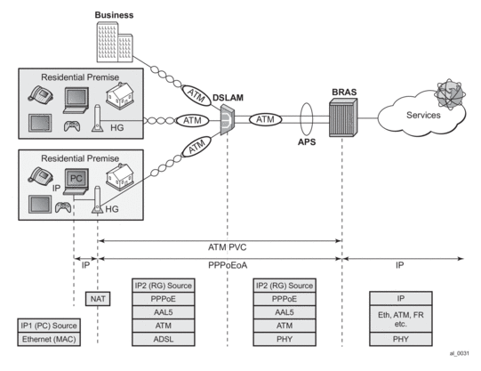
PPPoEoA implementation must allow multiple PPPoE sessions of the same subscriber to be carried over a single ATM PVC.
9.4.15.3. Hardware Support
This feature is supported on ATM MDA on:
- 7750 SR (SR-12, SR-7) platforms
- 7750 SR-c4/12 platforms
- 7450 ESS platforms in Mixed Mode.
This feature is implemented only on IOM3 based hardware.
ATM MDAs:
- 16 port ATM OC-3/STM-1 (single rate)
- 4 port ATM OC-3/12c/STM-1/4c (dual rate on a per port basis; oc3/stm1 or oc12/stm4; port speed can only be changed in groups of four ports).
Chassis modes B,C and D are supported.
PPPoEoA/PPPoA will NOT be supported on the following modules:
ASAP MDAs:
- 4 port channelized OC-3/STM-1 (IOM2-20G and IOM3-XP)
- 1 port channelized OC-12/STM-4
- 12 port channelized DS3/E3 (coax)
- 4 port channelized DS3/E3 (coax)
ATM CMA:
- 8 port T1/E1 ATM (RJ-48)
The 7750-c4/12 currently supports only the four port ATM MDA.
9.4.15.4. Termination Points within 7450 ESS and 7750 SR
PPPoA/PPPoEoA sessions are terminated on the access ATM SAP in IES and IP-VPN service context through subscriber/group interfaces.
However, for the wholesale/retail deployment scenarios, the ATM VCs are terminated on the LAC while the PPP(oE) sessions will be terminated on the LNS.
PPPoA/PPPoEoA is not supported in the wholesale/retail VRF model (wholesale VRF + retailer VRF). However it is supported in wholesale/retail MSAP model (capture SAP in VPLS that is mapped into a VRF).
9.4.15.5. PPPoA Encapsulation
PPP frames are transported over ATM using ATM AAL5 framing mechanism. This is defined in RFC 2364. In short, each PPP packet is appended by an 8-octet AAL5 trailer with some control information (16-bit length field and a 32-bit CRC being the most important). This new frame is not self-identifying, in other words, kind of payload it carries (PPP, IPv4, IPv6, ARP, MPLS, etc.) can not be identified. This means that if you want to send it as such, it can carry only a single protocol type which must be agreed upon in advance by configuration at each side of a PVC connection. Only then will both ends of the connection be able to recognize the payload type inside of it.
To add more flexibility to the payload type and allow multiple protocol types to be multiplexed within a single VC session, an additional header must be defined in the AAL-5 packet. This header which allows protocol multiplexing over ATM VC is called Link Layer Control (LLC) header. PPP transport over ATM using LLC is defined in RFC 2364, PPP over AAL5. A more extensive version for multiplexing protocols over VC is defined in RFC 2684 “Multiprotocol Encapsulation over ATM AAL5” (LLC/SNAP encap).
7450 ESS and 7750 SR supports these two types of PPPoA encapsulation:
- LLC (RFC 2364)LLC header is extended with a NLPID (Network Layer Protocol Identifier) which identifies the protocol type inside of the AAL5 frame. NLPID for PPP in LLC is 0xCF.
Figure 88: PPPoA LLC Encapsulation
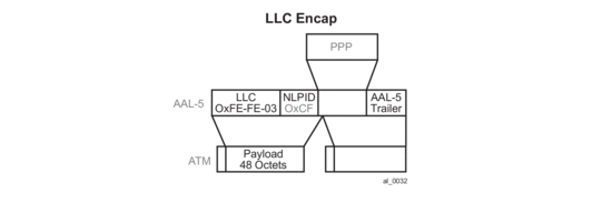 Possible CLI syntax:encapsulation aal5nlpid-pppThe ppp keyword in the aal5nlpid-ppp command is used to indicate that ppp is the only encapsulation that currently supported in NLPID.SNAP is an extension to LLC for protocols that are not defined in LLC NLPID. PPP protocol identifier is defined within NLPID and therefore it does not need additional SNAP header (this reduces the overall AAL5 header overhead).LLC/SNAP encapsulation is defined in RFC 2684, Multiprotocol Encapsulation over ATM Adaptation Layer 5, and it is needed for PPPoEoA encapsulation.
 - VC-MUXIn VC-MUX mode there is no additional (LLC/SNAP) header used for protocol multiplexing. Instead, VC endpoints must agree before hand on the payload type that they will transport. For PVCs this is done during the provisioning phase on each side of the connection. For example:encapsulation aal5mux-pppaal5mux-ppp will tell each end of the VC in advance that the payload inside of the AAL5 frame is PPP.
Figure 89: PPPoA AAL5MUX Encapsulation

9.4.15.5.1. PPPoEoA Encapsulation
Similar to PPPoA, two types of encapsulation are defined for PPPoEoA:
- Protocol multiplexing (Layer 2 bridging defined by additional headers - LLC/SNAP).
- VC-Multiplexing where payload type within a VC is agreed upon in advance by static configuration.
Both types are supported in our implementation:
- “Multiprotocol Encapsulation over ATM AAL5” (LLC/SNAP) defined in RFC 2684.This encapsulation adds support for protocols that are currently not defined in the LLC header. There are two basic types of encapsulations defined under this RFC:
- Routed
- Bridged
PPPoEoA encapsulation is defined as ‘Bridged’ where Layer 2 information is preserved through transitioning between two different Layer 2 network types (Ethernet -> ATM) which is shown in Figure 90.0xAA-AA-03 in the LLC header indicates the presence of the SNAP header.0x00-80-C2 in the OUI indicates that a bridged PDU is encapsulated.0x00-01 or 0x00-07 in PID indicates that the encapsulated Layer 2 network type is 802.3 Ethernet with or without preserved FCS.Figure 90: PPPoEoA Bridged LLC/SNAP Encapsulation
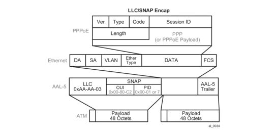
The CLI syntax is:
encapsulation aal5snap-bridged
- VC-MUXIn the VC-MUX mode there is no additional (LLC/SNAP) header used for protocol multiplexing. Instead, the VC endpoints must agree before hand on the payload type that they will transport. For PVCs this is done during the provisioning phase on each side of the connection. For example:encapsulation aal5mux-bridged-eth-nofcsaal5mux-bridged-eth-nofcs tells each end of the VC in advance that the payload inside of the AAL5 frame is an Ethernet frame. In this case, it accepts the frame and treat it as an Ethernet frame inside AAL5. The EtherType within the frame must be set to 0x8863 (PPPoE Discovey Phase) or 0x8864 (PPPoE Session Phase).The ‘-nofcs’ portion indicates that the FCS is not supported on those Ethernet frames.PPPoEoA encapsulation is shown in Figure 91.
Figure 91: PPPoA AAL5MUX Encapsulation
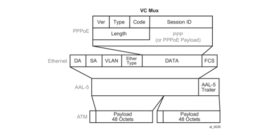
9.4.15.6. Encapsulation Summary
Figure 92: LLC/SNAP Encapsulation
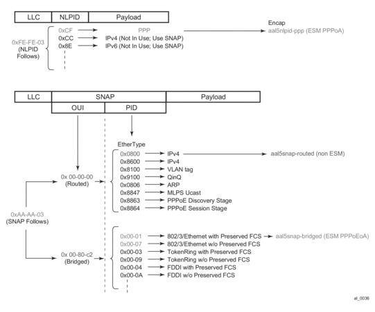
There is a 0-2Byte additional padding (optional) in the SNAP Bridged encapsulation header that is not shown in Figure 92. This padding, according to RFC 2684, is necessary to align the info field (payload of the Layer 2 encapsulated frame) on a 4-Byte boundary.
At the end the following types of ATM encapsulation are supported on 7450 ESS and 7750 SR in ESM:
aal5snap-bridged
This encapsulation type is used for PPPoEoA encapsulation with FCS or without FCS on ingress. On egress only frames without MAC FCS can be sent. PPPoE session type will be determined based on the EtherType in the Ethernet frame.
aal5mux-bridged-eth-nofcs
This encapsulation type is used for mux PPPoEoA sessions without MAC FCS.
aal5nlpid-ppp
This encapsulation type is used for LLC/NLPID PPPoA encapsulated packets.
aal5mux-ppp
This type encapsulation is used for PPPoA traffic without LLC/SNAP header (VC-MUX).
aal5auto (new command)
This encapsulation type is supported in ESM and it is used for auto detecting the encapsulation type. This is also called autosensing.
All hosts for the same subscriber will use the same encapsulation type.
9.4.15.7. Concurrent Support for Different Service Types on the Same Port
An ATM port on 7450 ESS and 7750 SR can concurrently support various service types. One service type can be mapped only to one VC. This would normally be the case if there is an aggregation network in front of 7450 ESS and 7750 SR . A Service Provider could run a variety of services over this aggregation network (ATM switches) connected on the same physical port within the routers.
For example, the following services can be run on the same physical port:
- PPPoA/PPPoEoA sessions connecting residential/business customers through a DSLAM to 7450 ESS and 7750 SR
- Providing access for xPIPE services
- Plain aal5snap-ip or vc-mux-ip PVC for Internet access
9.4.15.8. Restrictions in Scaled ATM MDA Mode
Note: ATM concatenation mode for Apipe is not supported in the 16K VC mode.
In the concatenated mode, cells are delayed so that they can be concatenated and delivered in a single packet over to pseudowires to the other side. Without concatenation, each cell is transported individually. The implication is that each cell is individually encapsulated into Eth/MPLS which results in wasted bandwidth on the link.
Support for the concatenated ATM pseudowires is not removed from the CLI in the 16K mode of operation:
Instead:
- Adding an ATM port or a connection profile on an MDA in 16-VC mode to an APIPE is disabled if the vc-type is set to atm-cell AND cell-concatenation is enabled.A:BNG>config>service>apipe# sap x/y/z:cp.w createMINOR: SVCMGR #2603 Cell-concatenation is not allowed on 16k VC-mode ATM MDAs
- cell-concatenation on an APIPE of the vc-type atm-cell is disabled if it already contains an ATM port or a connection profile.A:BNG>config>service>apipe>spoke-sdp>cell-concat# max-delay XMINOR: SVCMGR #2603 Cell-concatenation is not allowed on 16k VC-mode ATM MDAs
Note that regular VPI/VCI SAPs (sap:vpi/vci) are not allowed to be configured on an Apipe of vc-type atm-cell.
Cell-concatenation is supported on Apipe services with a VC on an ATM MDA in the 8-VC mode.
AAL5 SDU mode is continued to be supported.
9.4.15.9. QoS Implementation
In addition to our system QoS that is provided in the “Q” chip on IOM, the ATM MDA offers QoS capabilities at the ATM cell level. In the context of this document, the system QoS is referred to as ‘IOM QoS’ and to ATM MDA provided QoS simply as ‘ATM QoS’.
Both, IOM QoS as well as ATM QoS defined by Traffic Descriptors working at the cell level, play a role in the overall QoS for the SAP (or virtual circuit). ATM QoS defines rates of each VC stream and defines the behavior under port congestion. IOM QoS defines bandwidth allotment and the scheduling scheme for each service within a VC stream.
In general, both MDAs, ATM and ASAP, support four traffic categories:
- CBR
- Rt-VBR
- Nrt-VBR
- UBR
Figure 93: Scheduling on ATM MDA
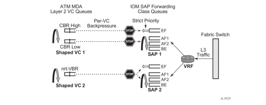
Each ATM traffic category is defined by a set of parameters, such as PIR, SIR, MIR, MBS and CDTV.
Currently, policing is supported only on ingress for CBR and VBR traffic classes. CBR traffic class police at PIR, while rt/nrt-VBR police at SIR.
Shaping is supported only on egress for CBR and rt/nrt-VBR traffic classes. CBR shapes traffic at PIR, while rt/nrt-VBR shape traffic at SIR. Egress shaping can be disabled only for nrt-VBR traffic class.
Scheduling at the ATM layer is shown in Figure 93. Shaped CBR and VBR traffic classes have two queues, an HP and an LP queue. Packets from IOM are marked according to scheduling priority of the Forwarding Class (expedited or best-effort) from which they were sent and are accepted into the ATM VC queue (HP | LP) accordingly. For example, at the IOM level packets from an expedited FC (queue) are marked as HP, and the packets from a best-effort FC (queue) are marked as LP. When these packets arrive to MDA, they will be admitted into appropriate queues, pending VC (or port) buffer availability.
Non-shaped VBR and UBR have only one queue at the MDA level.
In terms of the ATM QoS scheduling, CBR has the highest scheduling priority (strict priority) followed by rt-VBR (also strict priority). The remaining traffic classes (non-shaped VBR and UBR) are serviced in WRR fashion, the weight being their configured SIR (non shaped nrt-VBR) or MIR (UBR) rate.
There are several areas of QoS that are addressed in relation to integration of IOM QoS and ATM QoS:
- Association between the subscriber and ATM VC traffic descriptor.
- Rate adjustments between Layer 3 and ATM QoS rates due to difference in frame/cell sizes on which they operate.
- Per VP shaping.
9.4.15.10. Association Between the Subscriber and ATM VC Traffic Descriptor (QoS)
Each PPPoA PVC is of a certain traffic class – CBR, rt/nrt-VBR or UBR/UBR+MIR which along with other parameters is defined in the ATM traffic descriptor profile. For ATM service categories and traffic descriptors. There should be a uniform mapping between service offered and Layer 3 and ATM QoS.
Figure 94: ATM Traffic Descriptor Association with Subscriber
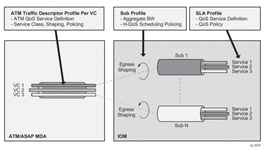
The ATM traffic descriptor (atm-td) is applied to a VC under the SAP CLI hierarchy. In this fashion, MDA related QoS (ATM QoS) is referenced outside of the subscriber context (SUB/SLA-profiles).
The following describes the operability:
atm-td for the VC is applied under the SAP:
and for MSAP:
The msap-policy is then invoked via LUDB, RADIUS or the default-msap-policy under the capture SAP.
This allows router to have preconfigured MSAP policies, each corresponding to a specific VC type with its own traffic-class parameters (CBR/rt-nrt-VBR/UBR.). Each subscriber with corresponding hosts is then associated with a msap-policy that determines the VC type.
A more flexible way to go about this would be to allow the subscriber to reference the atm-td directly by the sub-host at the host creation time, independently of the msap-policy. This is supported in the following manner:
- atm-td is referenced via a RADIUS VSA in the Access-Accept message.
- There are two VSAs, one for ingress and one for egress atm-td:
- alc-ingress-atm-td (ATTRIBUTE Alc-ATM-Ingress-TD-Profile 128 integer)
- alc-egress-atm-td (ATTRIBUTE Alc-ATM-Egress-TD-Profile 129 integer)
- Only the first host of the subscriber can overwrite the atm-td that is defined under the msap-policy or under the static SAP.
- Consecutive hosts (second, third, and so on) of the same subscriber will not have any effect on the atm-td of the VC. For example, if the second host tries to overwrite the existing atm-td with a different atm-td, it will fail. Once the atm-td is set via the Access-Accept message for the first host, it cannot be changed as long as the subscriber is active in the system. This implies that all hosts of the same subscriber will have the same atm-td.
- If another hosts of the same subscriber initiates a session with a different atm-td name in the Access-Accept message, the host will be created but the atm-td for the VC will not be changed. A trap/syslog will be generated with a ‘VC-parameter-mismatch:VSA ignored’ info message.
- atm-td change will not be supported through CoA.
The following guidelines should be followed in configuring ATM traffic descriptors:
- ATM policing is the only function that can discard ATM cells on an ATM MDA
- Ingress:
- ATM policing can only be enabled on ingress.
- Policing is disabled by default.
- Policing can only be enabled for the following traffic categories: CBT, rt-VBR and nrt-VBR.
- CBR police at PIR. CBR is CLP transparent (it does not look at the CLP bit – aggregate traffic policing).
- rt-VBR and nrt-VBR police at SIR and can operate either in CLP Significant (CLP marking) or CLP transparent mode (only relevant for Apipes and not for ESM).
- In CLP significant mode with policing enabled, traffic is policed at the PIR value, but it can be marked with CLP 1 if it exceeds the SIR rate (only relevant for Apipes and not for ESM).
- Ingress classification: the service category and CLP bits only affect Apipe traffic. If ATM traffic is terminated in the BNG, rely on the existing QoS classification implemented in the IOM.
- Egress:
- Shaping is supported only on egress. Traffic shaping is supported for CBR, rt/nrt-VBR service categories.
- ATM MDA is cell “lossless” — It sends backpressure to IOM which drops packets.
9.4.15.11. Per VP Shaping
VCs traversing the same DSLAMs will typically use the same VPI. To prevent overrunning DSLAM capacity (intermediate destinations) in case an aggregation network is in place (between BNG and a DSLAM), per VP shaping will be implemented.
Figure 95: VP Shaper
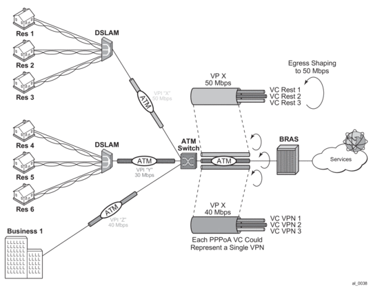
The shaping rate per VP and the VP service type is provisioned manually via a traffic descriptor on a per port level. The CLI syntax is:
Where the vpi is a VPI identifier and the egress-traffic-desc is the traffic descriptor id. Only traffic descriptors with service-category of cbr, rt-vbr and nrt-vbr can be used in VP Shapers. However, only the rate in the traffic descriptor can be changed on-the-fly, and not the service category (nrtVBR, rtVBR, CBR). A VP shaper can be added to or removed from active VCs.
CBR VP Shaper shapes cells at the exact PCR rate. There is no burst concept in CBR shaping. Excessive traffic is back-pressured towards the IOM (Q-chip).
The IOM will never send more frames to the ATM MDA than the MDA cannot buffer. This is implemented through a combination of software and hardware backpressure mechanisms. This backpressure mechanism utilizes a combination of hardware and software. Software backpressure aims to have around 100ms of traffic queued against a VC based on its configured shaping/scheduling rate, but being a software mechanism that is only a guideline. As ATM MDA detects more traffic that it can accept, a hardware backpressure is exerted.
A rt/nrt-VBR type VP Shaper has three parameters associated with it: PCR (peak cell rate), SCR (sustained cell rate) and MBS (maximum burst size at a peak rate). As long as there is enough MBR credit, traffic will be shaped at the PCR rate. Once all MBR credit (burst) is exhausted, traffic will be shaped at the SCR rate. Bursting above the SCR is configurable via the MBS parameter.
In both cases cells will be spaced at 1/PCR or 1/SCR as perfectly as possible with minimum jitter.
VP shaping is supported only when the ATM MDA is in max16k-vc mode. The maximum number of VP shapers per MDA to 128.
The maximum number of VCs that can feed into a single VP shaper is 16K. This includes the sum of all VC-ranges on the VP plus any statically configured VC on that VP.
VCs within the VP tunnel is serviced by a single scheduler assigned to each VP tunnel. The ATM VP shaper will condition the aggregate traffic for all ATM VCs within the VP tunnel. VCs within the shaped VP tunnel are degraded from the originally assigned service category to a common UBR service category (default traffic descriptor). If the VP shaper is removed from the VCs, the VCs will be reverted to their original service category. Scheduling between VCs will be WRR based with a weight parameter that is explicitly configured. The weights assigned to VCs within the VP tunnel are in range 1-255. By default, VCs are assigned a priority based on the originally assigned service category:
- VC degraded from CBR = wight 10
- VC degraded from rt-VBR = weight 7
- VC degraded from nrt-VBR = weight 5
- VC degraded from UBR+ = weight 2
- VC degraded from UBR = weight 1
The weight parameter is user configurable under the traffic descriptor hierarchy.
If weight is not specifically configured, the defaults are taken as described above.
The explicitly configured weight parameter is honored only on ATM MDA in the max16k-vc mode. On all other ATM capable MDAs (ASAP or ATM MDA in max8K-VC mode), the weight parameter is ignored.
Note that in the current ATM implementation there is already a WRR scheme in place based on internally calculated weights. This WRR scheme is used to service traffic from the VC queues of equal priority (where there are two queues per VC - a HiPrio and a LowPrio queue). Weights are assigned to VCs automatically based on the rate of the VC,
9.4.15.12. ATM/IOM QoS Integration
There are major differences between the QoS mode of operation at the ATM MDA level and the IOM level.
ATM QoS operates on fixed size cells that contain additional transport overhead. In addition, ATM shaping is very accurate so that traffic is paced into the ATM network with nodes that are sensitive to bursts (ingress policing). Buffering and service differentiation (number of queues) at the ATM layer is not as flexible as it is on the IOM level.
On the other hand, HQoS in the IOM is less accurate and less responsive to sudden traffic fluctuations (bursts). It operates on Layer 2 frame lengths. Bursts of traffic are usually let into the network more freely than the ATM network would like to accept.
To combine the extensibility of IOM HQoS with the stringent ATM QoS requirements, the two modes of operation are integrated.
The congestion in the ATM network is treated by using extensive IOM HQoS.
When the VC ATM queue becomes congested, it exerts backpressure to the subscriber queues in the IOM on the corresponding VC.
To avoid the condition where a VC becomes overly oversubscribed and excessive in exerting the backpressure, our HQoS in IOM has to be proactive and has to be able to detect congestion on the IOM level based on the ATM VC configured rate or the VP configured rate. IOM HQoS must deal with this congestion before it actually becomes the problem in the ATM layer. Occasional and short-lived backpressure from VCs, but persistent QoS backpressure and congestion at the ATM layer is avoided. A prerequisite for treating ATM congestion at the IOM level is to adjust the frame size in HQoS calculations (on all levels - including queues and aggregate rate limits) so that it reflects the ATM overhead associated with ATM transport (AAL5 encap, cellification).
9.4.15.12.1. Intermediate Node Rate Limit/Shaper
In many cases it is desired or even necessary to shape traffic per DSLAM. In the ATM network, a DSLAM corresponds to a VP (Virtual Path) which is at the ATM cell level identified by a Virtual Path Identifier (VPI). The VPI/VCI pair represents the addressing mechanism in the ATM network.
Another level of hierarchy is introduced into our HQoS model - an aggregate rate limit in the IOM that will correspond to the ATM VP shaper. The purpose of this new construct in the IOM is to help detect congestion at the IOM level before it becomes a severe problem at the ATM layer.
As a final solution, the HQoS hierarchy in the IOM is a 4-tier hierarchy consisting of:
- subscriber queues that are parented to the port scheduler
- egress agg-rate-limit that represents the egress aggregate subscriber rate
- tier-2 aggregate-rate-limit that represents the ATM VP rate limiter (related to DSLAM). This is a pure rate limiter and not a scheduler (it does not receive any scheduling opportunity).
- port-scheduler to which are subscriber queues parented. The port-scheduler delegates bandwidth to its children based on the priority levels associated with the children queues.
The four tiered hierarchy is needed to deal with:
- port congestion. The port bandwidth can be overbooked the desired service levels can still be ensured.
- ATM VP congestion. An ATM VP can be effectively protected from prolonged congestion that would result into significant backpressure to the IOM queues.
- subscriber congestion. Within the subscriber, bandwidth is managed within the subscriber bandwidth limit.
The four-tiered hierarchy looks like Figure 96.
Figure 96: Tier HQoS
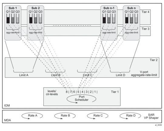
The key point in such HQoS model is that the port-scheduler delegates its available bandwidth to the subscriber queues directly according to the queue priority on a configured level. Higher priority queue are served over all subscribers before any lower priority queues, up to the limits imposed by the tier 1 and tier 2 aggregate rate limits.
9.4.15.12.2. Provisioning Aspects
The tier 2 aggregate rate limit that corresponds to the VP shaper on the IOM level is provisioned in the context of a vport. The vport is a container that is configured directly under the port and it can contain either an aggregate rate limit or another port scheduling policy (port scheduler). These two constructs (vport aggregate and V-port port scheduling policy) are mutually exclusive. In addition, if a V-port port scheduling policy is configured instead of the V-port aggregate, then the port scheduler cannot be used (currently two port schedulers applied under the same port cannot be used in a parent/children relationship).
The V-port aggregate have to have the agg-rate-limit defined explicitly. In other words, the rate cannot be implicitly inherited by configuration from the VP shaper traffic descriptor.
Example:
The association between the vport aggregate and the subscriber host is done in three ways:
- RADIUS attribute — a dest-string VSA that is matched against the string defined under the corresponding vport. This dest string VSA is returned via RADIUS at the subhost instantiation time.
- LUDB – similar to the RADIUS method. The dest-string comes from the LUDB instead from RADIUS.
- VP identifier (VPI) - The VPI is known to the CPM from the beginning of the session initiation process – raw (unknown encapsulation) packets and passed to the CPM. These raw packets contain VPI,VCI identifiers. The vport container for the subscriber is referenced implicitly via the VPI in the following fashion (Figure 97):
- CPM determines the VPI from the first packet for the session.
- ATM VP Shaper mapping: The VPI is used to make the subscriber association with the VP Shaper which is defined under the VP Shaping node: port>sonet-sdh>path>atm>vp. The VP Shaping node name must be the VPI number.
- Vport mapping: The vport-name in the port>sonet-sdh>path>access>egress>vport <vport-name> hierarchy is matched against the VPI number.
Figure 97: VPI Based V-Port <-> Subscriber Association
The association method (automatic via VPI or based on RADIUS/LUDB) between the subscriber host and the vport is defined under the SAP (or MSAP) where the subscriber resides. In most cases subscriber management is used with MSAPs.
This is the syntax:
The def-inter-dest-id stand for a ‘default inter-destination identifier’.
If the use-vpi method is used and the VPI derived from the incoming traffic points to a non-existing VP container, the association between the subhost and the V-port container will fail and a message/trap is logged. This however will not prevent the creation of the subhost that can be parented to the port-scheduler.
If the use-vpi is used on an Ethernet port where this parameter is not applicable, the parameter is ignored and defaulted to ‘string’. A message/trap is logged.
Note that if the vport contains an aggregate-rate-limit, then there is no need for the indication of a vport construct in the sub-profile or sla-profile of the subscriber. On the contrary, in case that the vport contains a port-scheduling-policy, the sla-profile template must contain the indication that the subscriber is tied to a vport (config>subscr-mgmt>sla-profile>egress>qos sap-egress-qos-policy-id vport-scheduler.)
9.4.15.12.3. HQoS Combinations
These are the possible HQoS combinations that are supported:
- port-scheduler assigned to path, agg-rate-limit assigned to vport, agg-rate-limit assigned to subscriber.
- port-scheduler assigned to path, no vport, agg-rate-limit or scheduler-policy assigned to subscriber.
- no port-scheduler assigned to path, port-scheduler assigned to V-port, agg-rate-limit or scheduler-policy assigned to subscriber.
- no port-scheduler assigned to path, no vport, scheduler-policy assigned to subscriber.
In case that the vport contains the agg-rate-limit, any subscriber host queue that is parented to a virtual scheduler will not be rate-limited by the vport aggregate rate. The queue will compete for bandwidth directly on the port's port scheduler, at the priority level and weighted scheduler group the virtual scheduler is port-parented to. If the virtual scheduler is not port-parented or if there is no port scheduler policy on the port, the host queue will be orphaned and will compete for bandwidth directly based on its own PIR and CIR parameters.
9.4.15.12.4. ATM Rate Adjustment
The difference in cell/frame overhead on the ATM level and IOM Level (Layer 2) lead to inconsistent behavior in integrated QoS. For example, IOM based QoS operates on Layer 2 frames (PPP header is included in rate calculations). On the other hand, ATM QoS operates on ATM 53byte cells. Each PPP frame with AAL5 overhead is segmented into 48-byte chunk cells prepended by a 5 byte ATM header. Assuming that ATM QoS operates on 53-octet cells, a significant rate discrepancy might arise from this difference.
For example, consider two flows:
Flow 1, 1000pps, PPP+IP packet size 190Bytes => L2 (IOM) QoS rate is 1520 kb/s
Flow 2, 1000pps, PPP+IP Packet size 232Bytes => L2 (IOM) QoS rate is 1856 kb/s
Assuming that VC MUX encap is used, and that AAL5 trailer (8 octets + padding) is used:
Flow 1 = AAL5 length is 190+8+48B_boundary_padding= 240Bytes => 5 ATM cells
Flow 2 = AAL5 length is 232+8+48B_boundary_padding= 240Bytes=>5 ATM cells
Each cell has a 5 byte header which translates into a 2120 kb/s rate for each flow.
As a result, more bandwidth is required at the ATM layer than the QoS on the IOM level has budgeted. Moreover, the two flows appear to be of the same rate at the ATM layer, even though the IP rate of flow 1 is ~20% less than the flow 2.
From the example above, Flow 1 consumes 40% more bandwidth configured at the ATM layer than it is given in IOM QoS. The rate adjustment depends on the packet size which additionally complicates conversion. This issue is more pronounced with smaller packet sizes.
An example is shown in Figure 98.
Figure 98: QoS Adjustment
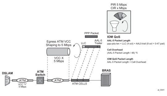
Depending on the session encapsulation (VC-MUX, LLC/SNAP) the packet length on which IOM QoS operates is adjusted.
The rates are adjusted on a per queue level, per subscriber egress agg-rate-limit level, per V-port aggregate level and on per port-scheduler level. Because the ATM termination points are on the BNG, there is a direct view of the encapsulation. The encapsulation information is supplied to the forwarding plane via the control plane.
The rate adjustment are examined in the following commands:
- frame-based-accounting under the qos>scheduler-policy hierarchy
- queue-frame-based-accounting under the sub-profile>agg-rate-limit hierarchy
- avg-frame-overhead under the queue hierarchy
- encap-offset under the sub-profile hierarchy
In PPPoA/PPPoEoA scenario there is no last mile rate adjustment (due to the difference in encapsulation) performed. It is assumed that the encapsulation in the last mile and in the intermediate mile is the same. In other words, it is assumed that the DSLAM does not add/change any encapsulation but instead it only acts as a VPI/VCI cross-connect. If the last mile encapsulation is PPPoA, then the intermediate encapsulation is considered to be PPPoA as well. Similar is valid for PPPoEoA encapsulation.
There are two configuration scenarios possible:
- The encap-offset command in the sub-profile is configured. This command overwrites any other command related to rate conversion that might be configured (frame-based-accounting, queue-frame-based-accounting, avg-frame-overhead, or avg-frame-size). The encap-offset command forces dynamic wire rates calculation in the intermediate mile (directly connected ports) on all levels in the QoS hierarchy. The wire overhead in the intermediate mile takes into account the length of the fixed ATM encapsulation, the variable length of AAL5 encapsulation (including AAL5 48bit boundary padding) and the ATM cellification overhead. The queue stats are also wire based. All calculations are performed in the data plane using the actual packet size. In other words, this command will ensure that the rates on the queue level and the subscriber aggregate level (either through virtual schedulers or egress aggregate-rate limits) are wire based. Port-scheduler and V-port rates are already by default wire based rates and this cannot be changed.
- The encap-offset command is not configured by default. In this case the other rate conversion related commands are in effect (frame-based-accounting, queue-frame-based-accounting, avg-frame-overhead, or avg-frame-size). The behavior is the following:
- Wire rates in the intermediate mile (directly connected ports) are based on the avg-frame-overhead command which is provisioned via CLI. If avg-frame-overhead is not provisioned via CLI, by default it is assumed to be 0[%] and the wire rates effectively become data rates (IP payload + IP header + PPP(oE) header + fixed ATM encapsulation).
- Queue stats (used in accounting) are always ‘data’ stats. This includes the IP Payload + IP header + PPP(oE) header + fixed ATM encapsulation.
- agg-rate-limit (subscriber or vport) rates are always wire rates (as defined in the first bullet – based on the avg-frame-overhead).
- Rates in the port-scheduler-policy (vport or physical port) are always wire based (rates (as defined in the first bullet – based on the avg-frame-overhead).
- The frame-based-accounting command under the scheduler-policy will affect rate calculation for virtual schedulers and queues:
- If this option is configured, the virtual scheduler and queue rates will be wire based.
- if this option is NOT configured, the virtual scheduler and queue rates will be data rates
- queue-frame-based-accounting configuration option under the subscriber agg-rate-limit command (in sub-profile) will affect rate calculations for queues. If this command is configured, the queue rates will be wire rates, otherwise they will be data rates
Avg-frame-size command in PPPoA/PPPoEoA is ignored.
Currently queue rates and subscriber virtual scheduler rates are allowed to be either data rates (one in Figure 99) or on-the-wire-rates (three in Figure 99). Port-scheduler rates, vport rates and the subscriber agg-rate-limit (in sub-profile) are always on on-the-wire rates.
Figure 99: ATM Wire Overhead
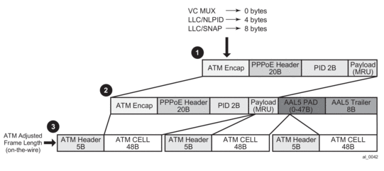
9.4.15.13. Subscriber Instantiation Use Cases
Note that multiple subscribers per single VC are not supported. However, multiple VCs per subscriber are supported.
The following displays examples of how subscriber hosts could be instantiated in PPPoA/PPPoEoA environment.
Case 1
- One host per subscriber.
- One ATM VC per subscriber.
- Authentication is done via RADIUS or LUDB.
- Authentication methods: PAP/CHAP or PADI for PPPoE.
- If there is no RADIUS/LUDB authentication, the subscriber-id should be by default the SAP (with VPI:VCI) with default sub-strings. For MSAP this would be configured under the msap-policy – all subs would have the same service in this case (SLA/SUB profiles).
Figure 100: Subhost per VC
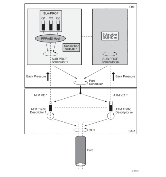
Case 2
- Multiple hosts per subscriber
- Single VC per host
- Multiple VCs per subscriber
- PPPoA or PPPoEoA
- Subhosts for the same subscriber can authenticate using a unique username or the same username
Figure 101: Multiple VCs per Subscriber
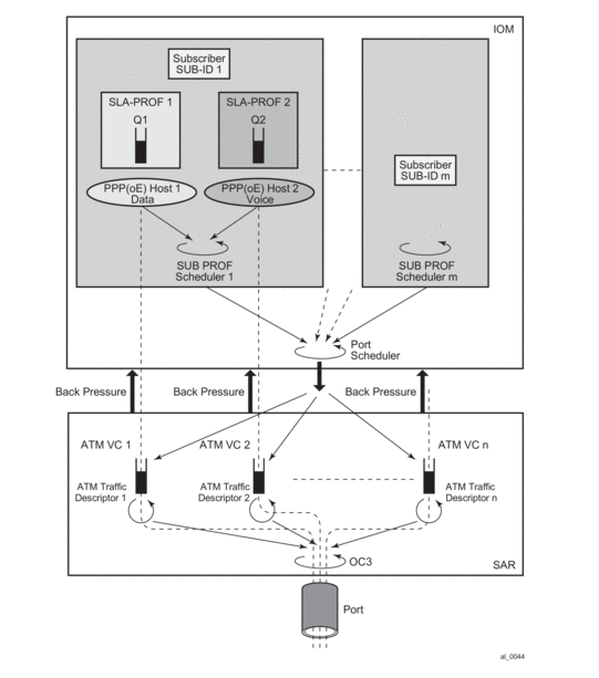
Case 3
- Multiple hosts per subscriber
- Singe VC
- PPPoEoA only
- Per host SLA-PROFILE instantiation
Figure 102: Multiple Hosts per Subscriber, Single VC
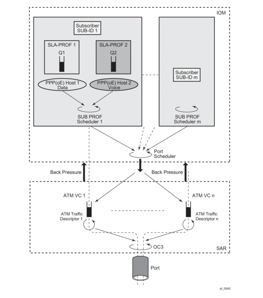
Case 4
- VP Shaping
Figure 103: VP Shaping
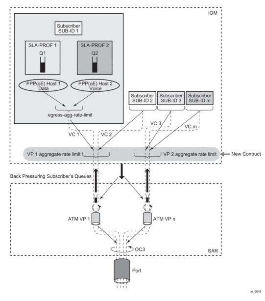
9.4.15.14. Authentication
Authentication for PPPoEoA is the same as in PPPoE:
- based on PADI
- based on PAP/CHAP
- No authentication
Authentication in PPPoA is based on:
- PAP/CHAP
- No Authentication — There is a small percentage of cases where this might be required.
An example of no authentication configuration for PPPoEoA would be:
In the case that there is no PAP/CHAP authentication, a PPPoE host can be identified by a MAC address, circuit/remote-id (inserted by the BNG) or service-name in PPPoE.
9.4.15.15. LUDB Access via Capture SAP
Access to LUDB via a capture SAP is enabled for this feature:
Note that if the authentication-policy (RADIUS authentication) is specified under the capture SAP, it (the RADIUS authentication) will take precedence over LUDB.
9.4.15.16. Encapsulation Autosensing
As previously discussed, these four static encapsulation types will be supported:
- aal5nlpid-ppp (LLC/SNAP for PPPoA)
- aal5snap-bridged (LLC/SNAP for PPPoEoA)
- aal5mux-ppp (mux PPPoA)
- aal5-mux-bridged-eth-nofcs (mux PPPoEoA)
These four types of encapsulation are supported for ATM MSAPs as well as for fixed configuration ATM SAPs.
In addition, the LLC/SNAP encapsulation type can be autosensed. This is called autosensing. The keyword for autosensing is aal5auto. An option is given to provision encapsulation statically, if needed.
The aforementioned encapsulation options (including autosensing) is visible only under the SAP hierarchy on group-interfaces and on capture SAPs in VPLS. This is allowed only in 16K-VP mode ATM MDA.
9.4.15.17. SAP Autoprovisioning
In order to simplify the provisioning of the subscriber access ports in the ESM context, a concept similar to managed SAP (MSAP) on Ethernet is introduced. In Ethernet MSAP, an ingress access SAP is automatically created upon receipt of the first (VLAN) tagged packet from the customer side (pending the authentication process).
In our ESM over PPPoA/PPPoEoA case, a number of PVCs is pre-provisioned that will initially be only in a provisioned (or listening, passive) state. This is sometimes referred as a bulk configuration of VC ranges. Once the initial ESM processing in the CPM is completed (for example, the user is authenticated), the ATM SAP is created in the appropriate context (VRF or GRT) and the ATM VC is activated. ATM VC activation means that the ATM VC is associated with a SAP.
The ratio between the maximum number of provisioned VCs vs the maximum number of active VCs on an MDA supporting PPPoA/PPPoEoA is 2:1. This amounts to 32K ATM VCs in the listening state. Out of the total 32K ATM VCs, 16K ATM VCs can be active simultaneously.
Obviously, there are some differences between the Ethernet MSAP processing and the ATM MSAP processing. On Ethernet there is not need to pre-configure VCs, while on ATM this is necessary due to complexity of ATM layer comparing to Ethernet.
Our current Ethernet based MSAP is configured under VPLS. The same approach is adopted for ATM capture SAP.
Since a combination of ESM over PPPoA/PPPoEoA VCs and other non PPPoA/PPPoEoA VCs on a single physical port is supported, ranges of VCs that will be supported in autoconfiguration are defined. ATM VCs outside this range are available for manual creation. Multiple ranges are necessary in order to address non-contiguous sets of VPI/VCIs.
The following is the CLI syntax:
Note that the capture SAP must be configured as ‘*/*’ in place of the VPI/VCI identifiers. Any other combination for the VPI/VCI identifiers is not allowed.
Up to 5 ranges are allowed per capture SAP. VCs configured in this way can carry a single PPP session per VC or multiple PPPoE sessions per VC. Ranges are not allowed unless the ATM MDA is in the 16K-VCs mode.
The total number of VCs that can be fed into a VP is 16K. This includes all VC ranges associated with the VP plus any statically configured VC on the VP.
9.4.15.18. PPP Nodes and ppp-policy
Differences in operation between PPP and PPPoE warrant creation of a new ppp node under the group-interface in the CLI that will cover PPP aspects of operation. The existing pppoe node under the group-interface is preserved in the CLI. This allows referencing different user-dbs for authentication purposes and different session parameters defined in the ppp-policy for each session type (pppoe or plain ppp).
PPP node under the group-interface is used to cover PPPoA operation while PPPoE node is used to cover PPPoE and PPPoEoA operation. ATM in PPPoEoA is just a transport and as such does not carry any information relevant to PPP operation (like PADx does in PPPoE).
For dynamic SAPs (managed SAPs), the same PPP(oE) related structures are referenced under the capture SAP hierarchy. Under the capture SAP there are no ppp/pppoe nodes (like they are under the group-interface hierarchy). In order to differentiate between ppp and pppoe clients, a new ppp-policy command is introduced in addition to the pppoe-policy command. The ppp-policy under the capture SAP is needed for the definition of session parameters before the group-interface (where normally session parameters are referenced) is determined.
Two commands for LUDB access are available under the same capture-sap hierarchy (pppoe-user-db and ppp-user-db).
The ppp-policy under the subscr-mgmt hierarchy contains PPP and PPPoE session parameters. PPP parameters are applicable to both session types (PPP and PPPoE) while PPPoE parameters are applicable only to PPPoE session type. The PPPoE parameters are ignored for PPP sessions.
9.4.15.19. MTU Considerations
MRU configuration option negotiated during the LCP phase in PPPoA is based on the following command:
By default, this command is disabled and consequently will negotiate the default MRU of 1500B, as long as the ATM port’s MTU can accommodate at least 1500B:
The MRU option in PPPoA refers to the PPP packet length (PID+Information+Padding) that is ATM encapsulated.
9.4.15.19.1. PPP(oE) Session Antispoofing
Antispoofing filters need to be in place in order to prevent the hijacking of a PPPoA/PPPoEoA session. For successful anti-spoofing, the following fields are accessible:
- Source IP address (PPPoA and PPPoEoA)
- VPI/VCI pair which is equivalent to the SAP (PPPoA/PPPoEoA)
- Source MAC Address (PPPoEoA only)
- session-ID (PPPoEoA only)
For locally terminated PPPoEoA subscriber hosts, access to all fields are required (a, b, c and d). Antispoofing is defined under the following hierarchy:
This behavior matches our current PPPoE behavior. The default antispoofing option is set to mac-sid, which means that the incoming traffic is checked against the source MAC address and the session-ID. Antispoofing under this hierarchy cannot be disabled.
The source IP address can be added to the source MAC and session-ID (mac-sid-ip).
Note that the group-interface is the lowest granularity at which options can be enabled. In other words, these two options (mac+sid or mac+sid+ip) cannot be changed at the SAP level.
The VPI/VCI pair is always be checked against the incoming traffic, regardless of the configuration option as the VPI/VCI pair is an intrinsic part of the SAP (similar to VLAN tags on Ethernet).
In case that a subscriber host is a routed host (managed routes), the nh-mac antispoofing option must be enabled under the managed sap (msap-policy) or group-interface->sap level. Otherwise, managed routes for the host would not be installed. The nh-mac option forces a lookup of the incoming packet based on the mac+sid of the originally created host (CPE device). Note that only the group-interface->sap>anti-spoof and msap-policy hierarchies contain the nh-mac option, and NOT the pppoe->anti-spoof hierarchy.
For locally terminated PPPoA subscriber hosts, only access to source IP address is available (src mac and session-ID fields are non-existent in PPP).
The default antispoofing is based on the VPI/VCI pair + IP. This cannot be changed by configuration, except when the session has managed routes or is a LAC session. In the case of managed routes (routed host) a lookup will be done based on the SAP (VPI/VCI) only. The anti-spoofing for PPPoA should be set to anti-spoof nh-mac, under msap-policy or grp-if>sap hierarchy even though PPPoA has no MAC address.
For LAC, the behavior is the following:
- For PPPoE traffic, antispoofing is always done based only on the SAP+mac+session-id.
- For PPP traffic, antispoofing is always based on VPI/VCI pair (SAP only). The IOM automatically determines whether IP based antispoofing can be done (e.g. no IP based antispoofing for LAC and managed routes).
There are two other nodes on which antispoofing can be configured:
A few points in regards to the above hierarchy:
- ip - This option can be only used in BSM mode. This is used only for IPoE.
- ip-mac – Lookup is performed based on the combination of the IP address and MAC address (incipient host). This is used for IPoE. For PPPoE, it will be overwritten by the configuration option under the group-interface-> ppp node (mac+sid or mac-sid+ip).
- nh-mac – Lookup is based on the MAC only for IPoE or mac+sid for PPPoE.
This is similar to the previous case (under the group-interface>sap hierarchy) with the exception that the pure IP option is not supported under the MSAP. The reason is that the IP option can only be used in BSM (under the SAP node) whereas MSAP can only be used in ESM (PPPoX).
Note that for IPoE, the entire control over antispoofing under the (M)SAP node, while for PPPoE, the anti-spoofing control is distributed between the (M)SAP node and the group-interface>ppp node.
9.4.16. Multi-Chassis Synchronization
Figure 104 shows the configuration under which synchronization of subscriber management information is performed. As depicted, a single access node aggregating several subscriber lines is dual- homed to redundant-pair of nodes.
Figure 104: Dual-Homing Configuration
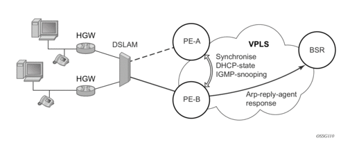
Enabling subscriber management features (whether basic subscriber-management (BSM) or enhanced subscriber management (ESM)) causes the node to create and maintain state information related to a given subscriber-host. This information is synchronized between redundant-pair nodes to secure non-stop service delivery in case of the switchover.
9.4.16.1. Overview
The synchronization process provides the means to manage distributed database (the Multi-Chassis Synchronization (MCS) database), which contains the dynamic state information created on any of the nodes by any application using its services. The individual entries in the MCS database are always paired by peering-relation, sync-tag and application-id. At any time the given entry is related two the single redundant-pair objects (two SAPs on two different nodes) and hence stored in a local MCS database of the respective nodes.
Internally, peering-relation and sync-tag are translated into a port and encapsulation value identifying the object (SAP) that the given entry is associated with. The application-id then identifies the application which created the entry on one of the nodes. There are three basic operations that the application can perform on MCS database. The MCS database will always synchronize these operations with its respective peer for the given entry.
The following principles apply:
- add-operation — Any dynamic-state created in the application is pushed to the MCS database. MCS then creates and synchronizes with the corresponding peer provided (if configured). The application in the peer node is then notified as soon as the entry has been created. Similarly, the application in the local node (the node where the state has been created) is notified that entry has been synchronized (MCS is “in-sync” state). This operation will be also used to modify existing MCS database entry.
- local-delete — The MCS database entry is marked as no longer in use locally and this information is sent to the peer node. If the information is no longer used by applications on both nodes (the application in remote-node has already issued local-delete before), it is removed from database.
- global-delete — The MCS database entry is removed from both nodes and from the application in the remote node.
The choice of the operation in corresponding situation is driven by the application. The following general guidelines are observed:
- An event which leads to a dynamic-state deletion on a standby chassis will be handled as “local-delete”.
- An event which leads to a dynamic-state deletion on an active chassis will be handled as “global-delete”.
- An exception to above the rules is an explicit “clear” command which will be handled as “global-delete” regardless of where the command was executed.
As previously stated, the MCS process automatically synchronizes any database operation with the corresponding peer. During this time, the MCS process maintains state per peer indicating to the applications (and network operator) the current status, such as in-sync, synchronizing or sync_down. These states are indicated by corresponding traps.
9.4.16.1.1. Loss of Synchronization and Reconciliation
Each time the connection between the redundant pair nodes is (re)established the MCS database will be re-synchronized. There are several levels of connectivity loss which may have different effect on amount of data being lost. To prevent massive retransmissions when the synchronization connection experiences loss or excessive delay, the MCS process implementation will take provisions to ensure following:
- In the case of a reboot of one or both nodes or establishing the peering for the first time, the full MCS database will be reconciled.
- In the case that the MCS communication is lost and then re-established but neither node rebooted during the connection loss, only the information not synchronized during this time will be reconciled (using sequence numbers helps identify information which was not synchronized).
- In the case that MCS communication is lost because of excessive delay in ACK messages but no information has been effectively lost, the MCS process indicates a loss of synchronization but no reconciliation is performed.
9.4.17. Subscriber Routed Redundancy Protocol (SRRP)
9.4.17.1. SRRP Messaging
SRRP uses the same messaging format as VRRP with slight modifications. The source IP address is derived from the system IP address assigned to the local router. The destination IP address and IP protocol are the same as VRRP (224.0.0.18 and 112, respectively).
The message type field is set to 1 (advertisement) and the protocol version is set to 8 to differentiate SRRP message processing from VRRP message processing.
The vr-id field has been expanded to support an SRRP instance ID of 32 bits.
Due to the large number of subnets backed up by SRRP, only one message every minute carries the gateway IP addresses associated with the SRRP instance. These gateway addresses are stored by the local SRRP instance and are compared with the gateway addresses associated with the local subscriber IP interface.
Unlike VRRP, only two nodes may participate in an SRRP instance due the explicit association between the SRRP instance group IP interface, the associated redundant IP interface and the multi-chassis synchronization (MCS) peering. Since only two nodes are participating, the VRRP skew timer is not utilized when waiting to enter the master state. Also, SRRP always preempts when the local priority is better than the current master and the backup SRRP instance always inherits the master’s advertisement interval from the SRRP advertisement messaging.
SRRP advertisement messages carry a becoming-master indicator flag. The becoming-master flag is set by a node that is attempting to usurp the master state from an existing SRRP master router. When receiving an SRRP advertisement message with a better priority and with the becoming-master flag set, the local master initiates its becoming-backup state, stops routing with the SRRP gateway MAC and sends an SRRP advertisement message with a priority set to zero. The new master continues to send SRRP advertisement messages with the becoming-master flag set until it either receives a return priority zero SRRP advertisement message from the previous master or its becoming-master state timer expires. The new backup node continues to send zero priority SRRP advertisement messages every time it receives an SRRP advertisement message with the becoming-master flag set. After the new master either receives the old master’s priority zero SRRP advertisement message or the become-master state timer expires, it enters the master state. The become-master state timer is set to 10 seconds upon entering the become-master state.
The SRRP advertisement message is always evaluated to see if it has higher priority than the SRRP advertisement that would be sent by the local node. If the advertised priority is equal to the current local priority, the source IP address of the received SRRP advertisement is used as a tie breaker. The node with the lowest IP address is considered to have the highest priority.
The SRRP instance maintains the source IP address of the current master. If an advertisement is received with the current masters source IP address and the local priority is higher priority than the masters advertised priority, the local node immediately enters the becoming-master state unless the advertised priority is zero. If the advertised priority is zero, the local node bypasses the becoming-master state and immediately enters the master state. Priority zero is a special case and is sent when an SRRP instance is relinquishing the master state.
9.4.17.2. SRRP and Multi-Chassis Synchronization
In order to take full advantage of SRRP resiliency and diagnostic capabilities, the SRRP instance should be tied to a MCS peering that terminates on the redundant node. The SRRP instance is tied to the peering using the srrp srrp-id command within the appropriate MCS peering configuration. Once the peering is associated with the SRRP instance, MCS will synchronize the local information about the SRRP instance with the neighbor router. MCS automatically derives the MCS key for the SRRP instance based on the SRRP instance ID. For example, an SRRP instance ID of 1 would appear in the MCS peering database with a MCS-key srrp-0000000001.
The SRRP instance information stored and sent to the neighbor router consists of:
- The SRRP instance MCS key
- Containing service type and ID
- Containing subscriber IP interface name
- Subscriber subnet information
- Containing group IP interface information
- The SRRP group IP interface redundant IP interface name, IP address and mask
- The SRRP advertisement message SAP
- The local system IP address (SRRP advertisement message source IP address)
- The Group IP interface MAC address
- The SRRP gateway MAC address
- The SRRP instance administration state (up/down)
- The SRRP instance operational state (disabled/becoming-backup / becoming-master/master)
- The current SRRP priority
- Remote redundant IP interface availability (available/unavailable)
- Local receive SRRP advertisement SAP availability (available/unavailable)
9.4.17.3. SRRP Instance
The SRRP instance uses the received information to verify provisioning and obtain operational status of the SRRP instance on the neighboring router.
9.4.17.3.1. SRRP Instance MCS Key
The SRRP instance MCS key ties the received MCS information to the local SRRP instance with the same MCS key. If the received key does not match an existing SRRP instance, the MCS information associated with the key is ignored. Once an SRRP instance is created and mapped to an MCS peering, the SRRP instance evaluates received information with the same MCS key to verify it corresponds to the same peering. If the received MCS key is on a different peering than the local MCS key an SRRP peering mismatch event is generated detailing the SRRP instance ID, the IP address of the peering the MCS key is received on and the IP address to which the local MCS key is mapped. If the peering association mismatch is corrected, an SRRP peering mismatch clear event is generated.
9.4.17.3.2. Containing Service Type and ID
The Containing Service Type is the service type (IES or VPRN) that contains the local SRRP instance. The Containing Service ID is the service ID of that service. This information is supplied for troubleshooting purposes only and is not required to be the same on both nodes.
9.4.17.3.3. Containing Subscriber IP Interface Name
The containing subscriber IP interface name is the subscriber IP interface name that contains the SRRP instance and its group IP interface. This information is supplied for troubleshooting purposes only and is not required to be the same on both nodes.
9.4.17.3.4. Subscriber Subnet Information
The subscriber subnet information includes all subscriber subnets backed up by the SRRP instance. The information for each subnet includes the Owned IP address, the mask and the gateway IP address. If the received subscriber subnet information does not match the local subscriber subnet information, an SRRP Subscriber Subnet Mismatch event is generated describing the SRRP instance ID and the local and remote node IP addresses. Once the subscriber subnet information matches, an SRRP Subscriber Subnet Mismatch Clear event is generated.
9.4.17.3.5. Containing Group IP Interface Information
The containing group IP interface information is the information about the group IP interface that contains the SRRP instance. The information includes the name of the group IP interface, the list of all SAPs created on the group IP interface, the administrative and operational state of each SAP and the MCS key and the peering destination IP address associated with each SAP. To obtain the MCS information, the SRRP instance queries MCS to determine the peering association of the SRRP instance and then queries MCS for each SAP on the group IP interface. If the local SRRP instance is associated with a different MCS peering than any of the SAPs or if one or more SAPs are not tied to an MCS peering, an SRRP group interface SAP peering mismatch event is generated detailing the SRRP instance ID, and the group IP interface name.
When receiving the remote containing group IP interface information, the local node compares the received SAP information with the local group IP interface SAP information. If a local SAP is not included in the SAP information or a remote SAP is not included in the local group IP interface, an SRRP Remote SAP mismatch event is generated detailing the SRRP instance ID and the local and remote group IP interface names. If a received SAP’s MCS key does not match a local SAP's MCS Key, an SRRP SAP MCS key mismatch event is generated detailing the SRRP instance ID, the local and remote group IP interface names, the SAP-ID and the local and remote MCS keys.
9.4.17.3.6. Remote Redundant IP Interface Mismatch
If the group IP remote redundant IP interface address space does not exist, is not within the local routing context for the SRRP instances group IP interface or is not on a redundant IP interface, the local node sends redundant IP interface unavailable to prevent the remote neighbor from using its redundant IP interface. An SRRP redundant IP interface mismatch event is generated for the SRRP instance detailing the SRRP instance, the local and remote system IP addresses, the local and remote group IP interface names and the local and remote redundant IP interface names and IP addresses and masks. The local redundant IP interface may still be used if the remote node is not sending redundant IP interface unavailable.
9.4.17.3.7. Remote Sending Redundant IP Interface Unavailable
If the remote node is sending redundant IP interface unavailable, the local node will treat the local redundant IP interface associated with the SRRP instances group IP interface as down. A Local Redundant IP Interface Unavailable event is generated detailing the SRRP instance ID, the local and remote system IP addresses, the local group IP interface name, the local redundant IP interface name and the redundant IP interface IP address and mask.
9.4.17.3.8. Remote SRRP Advertisement SAP Non-existent
If the remote node’s SRRP advertisement SAP does not exist on the local SRRP instances group IP interface, the local node sends local receive SRRP advertisement SAP unavailable to the remote node. An SRRP receive advertisement SAP non-existent event is generated detailing the SRRP instance ID, the local and remote system IP addresses, the local group IP interface name and the received remote SRRP advertisement SAP. Since SRRP advertisement messages cannot be received, the local node will immediately become master if it has the lower system IP address.
9.4.17.3.9. Remote Sending Local Receive SRRP Advertisement SAP Unavailable
If the local node is receiving local receive SRRP advertisements stating that the SAP is unavailable from the remote node, an SRRP Remote Receive advertisement SAP Unavailable event will be generated. This details the SRRP instance ID, the local and remote system IP addresses, the remote group IP interface name and the local SRRP advertisement SAP. Since the remote node cannot receive SRRP advertisement messages, the local node will immediately become master if it has the lower system IP address.
9.4.17.3.10. Local and Remote Dual Master Detected
If the local SRRP state is master and the remote SRRP state is master, an SRRP dual master event is generated detailing the SRRP instance ID and the local, remote system IP addresses and the local and remote group IP interface names and port numbers.
9.4.17.4. Subscriber Subnet Owned IP Address Connectivity
In order for the network to reliably reach the owned IP addresses on a subscriber subnet, the owning node must advertise the IP addresses as /32 host routes into the core. This is important since the subscriber subnet is advertised into the core by multiple routers and the network will follow the shortest path to the closest available router which may not own the IP address if the /32 is not advertised within the IGP.
9.4.17.5. Subscriber Subnet SRRP Gateway IP Address Connectivity
The SRRP gateway IP addresses on the subscriber subnets cannot be advertised as /32 host routes since they may be active (master) on multiple group IP interfaces on multiple SRRP routers. Without a /32 host route path, the network will forward any packet destined to an SRRP gateway IP address to the closest router advertising the subscriber subnet. While a case may be made that only a node that is currently forwarding for the gateway IP address in a master state should respond to ping or other diagnostic messages, the distribution of the subnet and the case of multiple masters make any resulting response or non-response inconclusive at best. To provide some ability to ping the SRRP gateway address from the network side reliably, any node receiving the ICMP ping request will respond if the gateway IP address is defined on its subscriber subnet.
9.4.17.6. Receive SRRP Advertisement SAP and Anti-Spoof
The group IP interface SAPs are designed to support subscriber hosts and perform an ingress anti-spoof function that ensures that any IP packet received on the group IP interface is coming in the correct SAP with the correct MAC address. If the IP and MAC are not registered as valid subscriber hosts on the SAP, the packet is silently discarded. Since the SRRP advertisement source IP addresses are not subscriber hosts, an anti-spoof entry will not exist and SRRP advertisement messages would normally be silently discarded. To avoid this issue, when a group IP interface SAP is configured to send and receive SRRP advertisement messages, anti-spoof processing on the SAP is disabled. This precludes subscriber host management on the SRRP messaging SAP.
9.4.18. PPPoE MC Redundancy
This feature minimizes the downtime for PPPoE clients in an ESM environment when a single node fails.
But it is not necessary that an entire BNG fails before it triggers the corrective action. The solution outlined in this document will natively include protection against interfaces and line card failures within the BNG. The redundant (protective) entity, however, does not reside within the same BNG on which the failure occurs but instead it is on a separate BNG node.
The PPPoE MC Redundancy is based on SRRP and MC-LAG because SRRP is already established in ESM providing IPoE MC Redundancy. With some modifications, SRRP approach is adopted to PPPoE deployments.
9.4.18.1. Hardware Support
This feature is supported on the following platforms:
- 7750 SR-7/12
- 7750 SR-c4/12
- 7450 ESS in mixed chassis mode.
MCS across different platform types (7750 SR-7/12, 7750-c4/12, 7450 ESS) is not supported. For example, MCS between 7750 SR-7/12 and 7750-c12 is not supported.
This feature is supported in the following chassis modes: B, C, D and SR Mixed Mode (IPv6 on IOM3 while IOM1 cards can be present in the same system).
IPv4 functionality is supported on IOM2 cards and IPv4/IPv6 on IOM3 cards.
Note: ESM v6 is supported only on IOM3 cards. IPv6 forwarding in ESM between IOM3 and IOM2 cards is not supported for example, if the access side is IOM3 and the network side is IOM2. However, plain routing (non-ESM related) is supported between these two cards.
9.4.18.2. SRRP Considerations for PPPoE
SRRP is based on VRRP whose purpose is to provide a default gateway redundancy for clients sharing the transport medium such as Ethernet. IPoE would be a typical example of this where IPoE clients use a virtual IP and MAC address that is shared between two default gateway nodes in the Master/Backup configuration. SRRP supports only two nodes in a cluster but VRRP allows multiple nodes to be configured in a cluster with a priority that will determine which node will assume Mastership. Although it is mandatory for the proper operation of IPoE clients that the same SRRP IP address is shared between the two BNG nodes providing redundancy, having the same SRRP IP address is not necessary for the operation of SRRP itself. In other words, SRRP itself (Master/Backup states) will work with different SRRP IP addresses on each node. Same is valid for MAC addressing. It is possible by configuration that the redundant BNG nodes use different IP/MAC addresses on a pair of SRRP instances.
Upon a switchover, a gratuitous ARP is sent from a newly selected active node so that each IPoE client can update the ARP table, if the MAC address has indeed changed (it does not have to). More importantly, if an Layer 2 aggregation network is in place between the BNG and the IPoE client, all intermediate Layer 2 devices will have to update their port-to-mac mappings (Layer 2 FIB). The above described process will ensure proper packet addressing on the IPoE client side as well as the proper forwarding path through Layer 2 aggregation network to the newly activated BNG.
When considering PPPoE in conjunction with SRRP, keep in mind that PPP protocol (point-to-point protocol) is adopted for the Ethernet (shared medium) by enabling an extra Ethernet related layer in PPP that allows sharing of point-to-point sessions over Ethernet (shared medium). The result is a PPPoE protocol designed to ‘tunnel’ each PPP session over Ethernet.
PPPoE is not aware of ARP (Address Resolution Protocol) and it will not react to gratuitous ARP packets sent by a newly active BNG. The destination MAC address that PPPoE clients will use when sending traffic is determined not by ARP but by the PPPoE Discovery phase at the beginning of the session establishment. This originally discovered destination MAC is used throughout the lifetime of the session. This has a couple of consequences:
- If SRRP is used for PPPoE then the ‘SRRP’ MAC address between the redundant BNG nodes must be shared. It is not allowed to use a unique ‘SRRP’ MAC address per BNG in the redundant pair of BNG nodes (as it is allowed today for IPoE). Every PADx conversation is based on the SRRP shared MAC address, that is, the PADO reply must have the shared SRRP MAC address as the source MAC. This has a significant impact on the operation of MSAP in conjunction with this feature.
- Since PPPoE sessions are not ARP aware, the only purpose of the gratuitous ARP would be to update the Layer 2 FIB in the aggregation network (and not the PPPoE client destination MAC address). For IPoE, the gratuitous ARP is sent for ALL subnet gateway IP addresses found under the subscriber interface over either all SAPs (default) or top-tags only. For PPPoE, the gratuitous ARP is sent only for the system IP address. The purpose of the gratuitous ARP in PPPoE scenario is only to update Layer 2 network path which is otherwise IP unaware. It is not necessary to send the gratuitous ARP for every default-gateway address found under the subscriber-interface. Since this feature is only applicable to PPPoE deployments, therefore, only PPPoE is present under the group interface. This is indicated by the following command under the SRRP node:
9.4.18.2.1. SRRP Fact-Checks
- Once Multi-chassis Synchronization (MCS) for subscriber management and SRRP is enabled, both BNG nodes, Master and Backup will in general forward packets (for subscribers) in both directions.
- Traffic flows through an SRRP enabled node according to the entries in the SRRP sync database and the SRRP state of the node:
- Backup SRRP directs downstream traffic over the redundant-interface towards the Master SRRP node. If the redundant interface is unavailable, traffic is sent directly to the subscriber.
- Master SRRP always directly forwards the downstream traffic towards the subscriber.
- In the upstream direction, the active SRRP node accepts subscriber traffic addressed either to the MAC address of the SRRP active group OR the native interface MAC address.
- The standby node accepts in the upstream direction only packets addressed to its native interface MAC address.
- If both SRRP nodes become Masters then both forward traffic to/from subscribers unaware of the link failure somewhere in the Layer 2 network. As a result, downstream traffic can be blackholed. Whether downstream traffic will be lost depends on the native routing on the network side, which is unaware of the failures in the aggregation network.
9.4.18.3. State Synchronization
PPPoE sessions are synchronized between the redundant BNG nodes. The subscriber synchronization is achieved through Multi-Chassis Synchronization (MCS) protocol in a similar way it is performed for IPoE.
Two keywords, ipoe and pppoe enable a more granular control over which type of subscribers the MCS should be enabled.
Subscriber synchronization is important for following reasons:
- Forwarding of downstream traffic between the redundant BNG nodes through a redundant interface is an artifact of how natural routing steers traffic through the network.
- Subscriber instantiation on the node which did not originally create subscriber session. This drastically reduces downtime during the SRRP switchover.
- Monitors operational aspects of the subscriber management through show commands.
9.4.18.3.1. PPPoE Multi-chassis Synchronization (MCS) Model
PPPoE MCS model is based on SRRP synchronization and can be used in a centralized or distributed environment with or without Layer 2 aggregation network in-between DSLAMs and BNG nodes. The failure detection speed is dependent on SRRP timers. Traffic load can be balanced per SRRP group over the two links. In this model (Figure 105), PPPoE states are synchronized between the redundant BNG nodes. If one BNG fails, the newly activated BNG sends out a ‘MAC update’ (gratuitous ARP) message prompting the intermediate Layer 2 nodes to update their forwarding tables so that forwarding can resume. The SRRP timers can be configured in the sub-second range. In reality, the limiting factor for timer values is the scale of the deployment, in particular the number of SRRP groups per node.
Figure 105: Fully Redundant “Statefull 1:1” Model
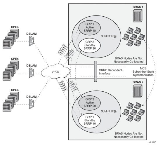
9.4.18.4. Traffic Control and Redundant Interface
To preserve QoS and Accounting, subscriber’s traffic must flow in both directions through the Master BNG node.
In the upstream direction, this is always true as traffic is steered to the master SRRP node just by the virtue of SRRP operation.
In the downstream direction which represents bulk of traffic, SRRP can not be relied up on to steer traffic through the Master node. This poses a problem in a very common environment where IP subnets are shared over multiple group-interfaces with SRRP enabled. A particular subnet will be advertised to the network side from both BNG nodes, Master and Backup. Natural routing on the network side will determine which BNG node will receive subscriber’s traffic in the downstream direction. If the Backup SRRP node receives the traffic, it cannot simply send the traffic directly to the access network where the subscriber resides by just inserting the source MAC address of the SRRP instance in the outgoing packet. This would break the operation of SRRP. Instead, the Backup BNG node must send the traffic to the Master BNG node via a redundant-interface. The Master SRRP node would then forward traffic directly to the subscriber. Source MAC address of this traffic would then be the MAC address of SRRP instance. This traffic shunting over the redundant interface can result in a substantial load on the link between the two BNG nodes.
The increase in shunted traffic can quickly become an issue if the redundant BNG nodes that are not collocated. To minimize the shunt traffic, more granular routing information must be presented to the network core. This would lead to more optimal routing where downstream subscriber traffic would be directed towards the Master BNG node, without the need to cross the redundant interface. The downside of this approach is that this would further fragment the IP address space within the network core. In the extreme case where /32 (subscriber) IP addresses are advertised, the churn that /32s can cause in the core routing would most likely be unsustainable. In this case, routing updates in the core would be triggered by subscribers coming on/off-line.
Optimal operation would call for the shunt traffic to be eliminated and at the same time, a high IP route aggregation on the network side is achieved. The existence of the shunt traffic stems from the fact that routing protocols advertise subscriber subnets into the network with no awareness of the SRRP activity state (Master/Standby). To address this problem along with better aggregation of advertised subnets, two SRRP enhancements are introduced:
- SRRP fate-sharing
- SRRP aware routing
Both of this concepts are described in the ‘SRRP Enhancement on page 1214” section.
Traffic destined to/from the subscriber is forwarded under the condition that the subscriber-interface is operationally UP. This applies also to shunting of downstream subscriber traffic from the STANDBY to MASTER node. It is always necessary to keep the subscriber-interface operationally UP by configuring a dummy group-interface with a oper-up-while-empty command under it. This is especially true for the MC-LAG which causes the messaging SAP on the STANDBY node always to be in the INIT state. In case that MSAPs are used on such group-interfaces, the group-interfaces would be also operationally DOWN, causing the subscriber-interface to be operationally DOWN.
9.4.18.4.1. Subnet Assignment and Advertisement - Option ‘A’
A single IP subnet is used for all subscribers terminated within the redundant BNG nodes. The upside of the Option ‘A’ is that it offers aggregated IP addressing in the network core per pair of redundant BNG nodes. The downside is that the subscriber termination point (active BNG for the SRRP group) is hidden from the network core. Since both BNG nodes share the same IP subnet for the subscribers, the natural routing can cause downstream traffic to be sent to the standby BNG which in turn will have to shunt the traffic to the active BNG. It is likely that half of the traffic will be shunted over the redundant-interface with this approach. This scenario is shown in Figure 106.
Figure 106: Shared Subscriber IP Space
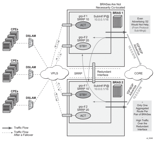
9.4.18.4.2. Subnet Assignment and Advertisement - Option ‘B’
With the option ‘B’, an IP address pool (or subnet) can be allocated per group of SRRP instances that are in the Master state. The routing decision on the network side is further influenced by the static increase of the metric of the advertised route on the BNG node hosting the active SRRP groups (Figure 107).
This approach would cause greater IP space segmentation in the network core, but at the same time, it would indirectly provide more information about the subscriber whereabouts and thus minimize or eliminate the shunt traffic during the normal operation. However, in the case of a SRRP switchover, the shunt traffic would ensue. The amount of the shunted traffic would depend on the scale of the failure. From the Figure 107, it can be concluded that:
- In the depicted scenario on Figure 107, there is no shunted traffic.
- If any of the SRRP instances transitions out of the Master state, traffic for an entire IP network associated with this failed SRRP instance would be shunted. The reason for this is that the advertised route metric is static and it does not follow changes in SRRP state.
Figure 107: Option ‘B’ – IP Subnet per Active SRRP Group

9.4.18.5. MSAP Considerations
As per RFC 2516 (PPPoE), this has the implications on the operation of the capture SAP. In IPoE environment, the initial DHCP traffic related to host establishment will use its native MAC of the physical port on the router. Once the group-interface is learned (later in the process, via RADIUS or msap-policy), the MAC address is switched to SRRP MAC address (virtual MAC). The IPoE client will adapt easily to this change. On the contrary, for the proper operation of PPPoE with SRRP, the initial destination MAC address learned by the PPPoE client does not change during the lifetime of the session.
This is ensured by indirectly referencing the grp-if under the capture SAP:
With this approach the grp-if is nailed during the session initiation phase by referencing the SRRP instance in track-srrp statement (SRRP is a group interface-wide concept). RADIUS returned grp-if name must match the one on which referenced SRRP instance runs.
The capture SAP of the form
assumes that there is only one grp-if associated with all msaps under this capture SAP.
A check is put in place to make sure that the MAC addresses associated with the SRRP instance is the same as the MAC address of the associated capture SAP. A log is raised if there is a discrepancy between the MAC addresses while the grp-if is operationally UP. If there is a MAC address change (user misconfiguration) then the existing PPPoE sessions will time out and the new sessions will fail to establish until the condition is corrected.
9.4.18.6. Unnumbered Interface Support
For unnumbered subscriber-interface support in PPPoE, the gateway IP address that is used to send gratuitous ARP is not available. For this reason, the system IP address is used to send gratuitous ARPs. Gratuitous ARP is used to update the Layer 2 network forwarding path towards the BNG node in the upstream direction.
The system IP address is used automatically if the subscriber interface is unnumbered.
9.4.18.7. Compatibility with MC-LAG
SRRP for PPPoE works in an environment where MC-LAG is enabled. For example, the standby LAG link automatically puts the SRRP node in a Backup state and the SRRP becomes master on the active MC-LAG link. It is important that the SRRP on the standby leg of the MC-LAG is forced into a Backup state, or any new state that will force the downstream traffic to use the redundant interface.
Traffic destined to/from the subscriber is forwarded under the condition that the subscriber-interface is operationally UP. This applies also to shunting of downstream subscriber traffic from the STANDBY to MASTER node. It is always necessary to keep the subscriber-interface operationally UP by configuring a dummy group-interface with a command oper-up-while-empty under it. This is especially true for the MC-LAG which causes the messaging SAP on the STANDBY node always to be in the INIT state. In case that MSAPs are used on such group-interfaces, the group-interfaces would be also operationally DOWN, causing the subscriber-interface to be operationally DOWN.
9.4.18.8. IPv6 Support
Prerequisite for MC IPv6 Redundancy is to synchronize PPPoEv6 and IPoEv6 subscribers between the nodes via MCS.
In PPPoE environment, SRRP is used to refresh the forwarding path (MAC addresses) in the access aggregation network (via gratuitous ARP). SRRP ensures that the upstream traffic is steered to the Master BNG node. In the downstream direction, the Backup BNG directs traffic over to the Master BNG node via redundant-interface.
The IPv6 functionality currently relies on IPv4 based SRRP and IPv4 based redundant-interface. In other words, IPv4 is required to run on the access side as well as on the redundant-interface.
The redundant-interface is used in the downstream direction. Traffic arriving on the network links on the Standby node is shunted over to the Master node over the redundant-interface. This is required to ensure consistent QoS and accounting functionality across the nodes (upstream and downstream traffic on the access links for a subscriber must traverse the same BNG node). There is no IPv6 related CLI associated with the redundant-interface.
All IPv6 subscriber traffic that arrives on the Standby node in the downstream direction is automatically shunted over the IPv4 redundant-interface to the Master node. When IPv6 traffic arrives over the redundant-interface on the Master node, it is either PPPoEv6 encapsulated or left as plain IPoEv6 before it is forwarded to the subscriber.
In the upstream direction (AN->BNG) the behavior is the following:
- PPPoEv6On the switchover, gratuitous ARPs (gARP) is sent from the new Master on each vlan. The IP address in gARP is the IPv4 gw-ip address or the system IP in the case of unnumbered interfaces. This updates the Layer 2 network path with the proper SRRP MAC address.
- IPoEv6IPv4 based SRRP is used to update the Layer 2 forwarding path in the case of a switchover. A gratuitous ARP is sent in the same fashion as it is used for IPoE v4 hosts. Router Advertisements (RA) are not sent out in the case of the switchover.However, the two BNG nodes share the same virtual Link Local (LL) IPv6 address. This address is used by the clients as a default-gw and only the Master BNG advertises this LL address in RAs. RAs are suppressed on the Standby node. As already mentioned, RAs are not sent during the switchover. RAs are sent:
- When the client first gets established – this is how the client learns its default-gw (in PPPoE case RA can also be used for SLAAC – stateless address configuration).
- As a reply to Router Solicitations messages sent by the clients.
- Periodically to each client.
Note that RAs are unicasted to each client.Neighbor Advertisements (NA) used for address resolution are sent only from the Master. NA has the SRRP MAC address in the target link layer option on SRRP enabled group interfaces (on non-SRRP enabled group-interfaces, NAs contains the group interface MAC address).The LL IPv6 address must be the same on both nodes. In addition, the gw-mac address must be the same on both nodes. The IPv6 clients will not be aware of the switchover and therefore they will not send NS to solicit the update of its neighbor cache with the possibly different gw-mac address.The syntax to configure the LL address on the subscriber interface is the following:
Note that the current version of SRRP relies only on IPv4 routes. The connection between SRRP and IPv4 routes is done via the subnets with gw IP addresses defined under the subscriber-interfaces in the ESM context. This connection is needed so that SRRP can send Gratuitous ARP properly.
These are the cases for PPPoEv6 MC Redundancy that are supported:
- unnumbered subscriber-interfaces (config>service>subscriber-interface hierarchy)
- numbered IPv4 subscriber-interfaces (config>service>subscriber-interface hierarchy)
- numbered IPv4 AND IPv6 subscriber-interfaces (config>service>subscriber-interface and config>service>sub-if>ipv6 hierarchy)
numbered IPv6 only subscriber-interfaces (config>service>sub-if>ipv6 hierarchy) is not supported
9.4.18.9. Considerations with Local DHCP Server
When local DHCP Server redundancy/synchronization is used, using address-range failover local | remote, in conjunction with PPPoE in multi-chassis environment, both DHCP servers must be referenced under the corresponding group-interface on each node. For address-range failover access-driven configurations only one DHCP server must be referenced.
Otherwise, the PPPoE clients will not be synchronized via MCS.
Note that this is not the requirement in the IPoE environment. In the IPoE environment, it is enough that the DHCP server points to the IP address of the local DHCP server. If the IP lease is originally assigned by the peer DHCP server, the request for renewal is automatically forwarded to the remote DHCP server by the virtue of the IP address of the original DHCP server that is included in the renewal request.
It is necessary for the successful renewal of the IP address on the remote DHCP server, that the remote DHCP server has a valid return path back to the gi-address of the forwarder of the renewal request.
9.4.18.10. Redundant Interface Considerations
In PPPoE dual-chassis environment without the redundant-interface in place, SRRP aware routing should always be used. Otherwise, if the downstream traffic arrives on the backup node, it will get forwarded directly to the client over the access network (assuming that the access network is operational) with the source MAC address of the group-interface (instead of gw-mac). This grp-if MAC address is different from the MAC address (gw-mac) negotiated during the initial PPPoE phase, and therefore, this traffic will be dropped by the client. It must be ensured that the downstream traffic is always attracted to the Master node in the absence of redundant.
9.4.19. Routed Central Office (CO)
9.4.19.1. Layer 3 Subscriber Interfaces
On regular interfaces in an IES or VPRN service, only one SAP can be associated. A group-interface allows multiple SAPs to be configured as part of a single interface. All SAPs in a single group-interface must be within the same port. Since broadcast is not allowed in this mode, forwarding to the subscriber is based on IP/MAC addresses information gathered by the subscriber management module and stored in the subscriber management table. These entries are based on both static and dynamic DHCP hosts. Routed CO must be used with standard subscriber management or enhanced subscriber management. DSLAMs are typically deployed with Ethernet interfaces.
This model is a combination of two key technologies, subscriber interfaces and group interfaces. While the subscriber interface define the subscriber subnets, the group interfaces are responsible for aggregating the SAPs.
As depicted in Figure 108, an operator can create a new subscriber interface in the IES or VPRN service. A subscriber interface allows for the creation of multiple group interfaces. The IP space is defined by the subnets of the subscriber interface’s addresses. Figure 108 shows the details of group interface A.
Figure 108: Subscriber Interface in an IES/VPRN Service
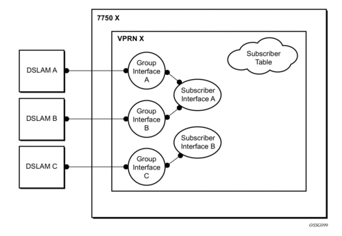
Figure 109: Details of a Group Interface
Figure 110 shows a network diagram where the DSLAM are connected directly to a Broadband Service Router (BSR) providing access to an IP subnet. Subscribers from multiple DSLAMs can be part of the same subnet. Note that BSR is also referred to as Broadband Network Gateway (BNG).
Figure 110: Aggregation Network with Direct DSLAM-BSE Connection
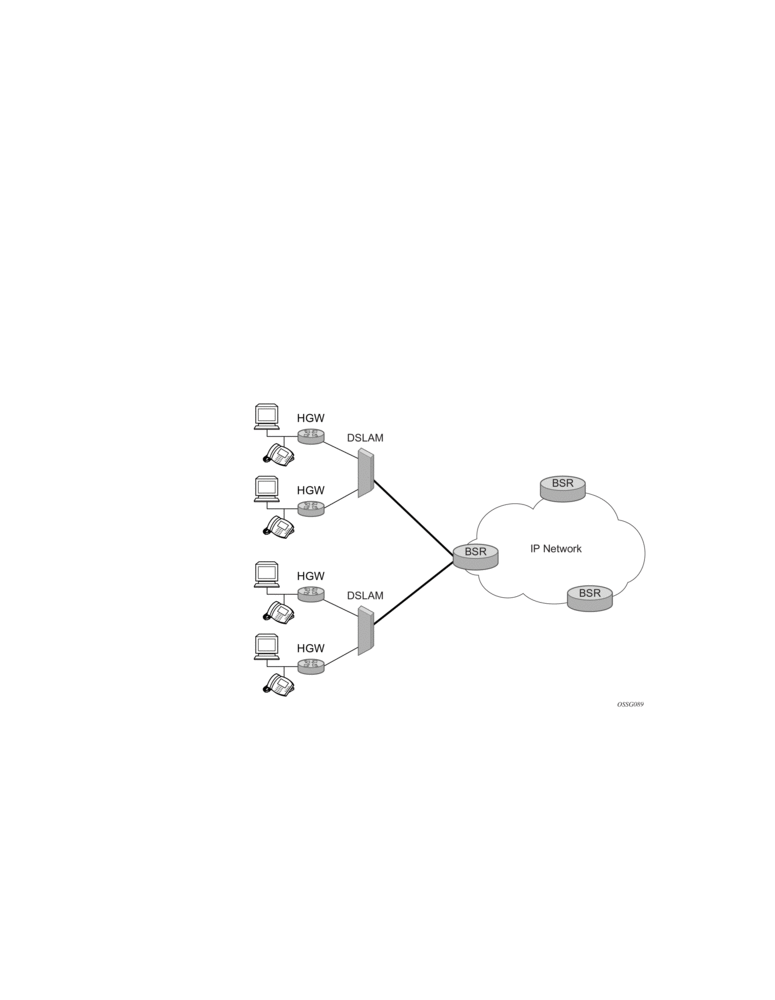
The BSR can be configured with multiple subnets, allowing subscribers to be part of a single subnet as well as providing mechanisms for re-addressing or expanding existing services without affecting existing users.
Figure 111: Detailed View of Configurable Objects Related to Layer 3 Subscriber Interfaces
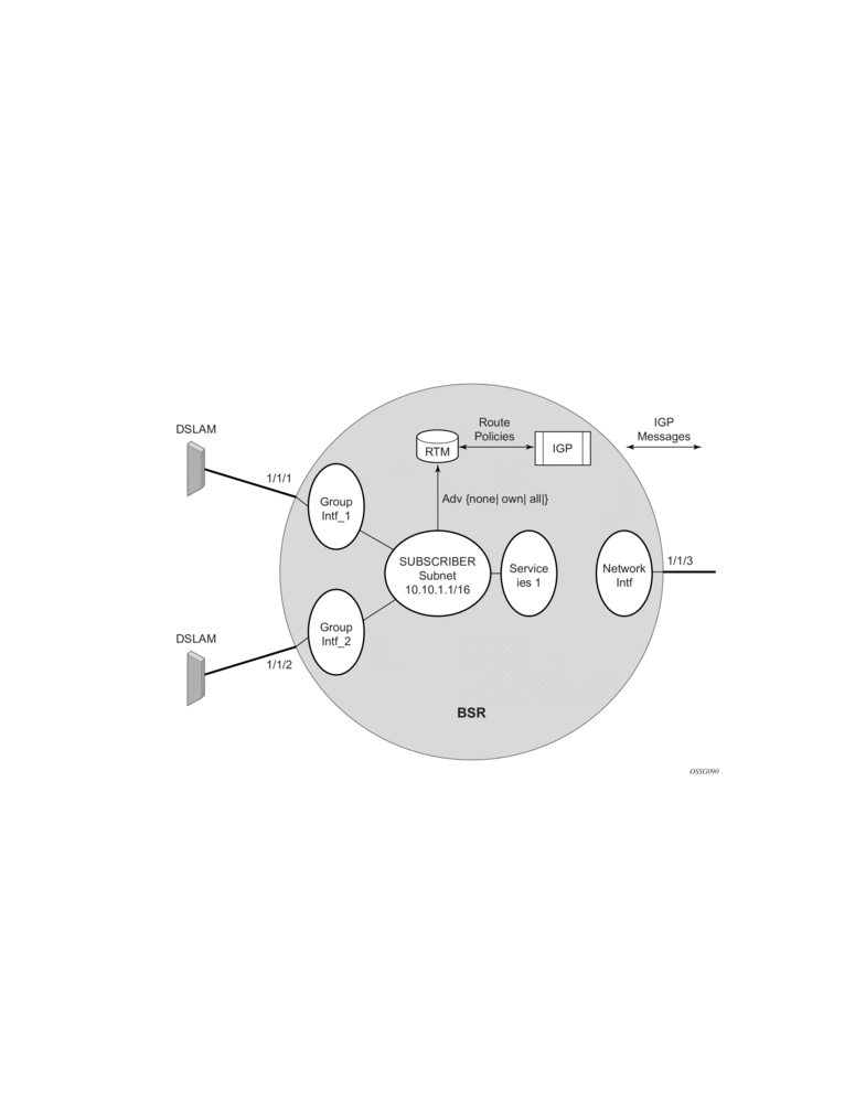
Figure 111 shows a detailed view of a router and the configuration objects implemented to support Layer 3 subscriber interfaces.
- A subscriber service is defined by an IES Service. One or more IES services can be created.
- Each IES service concentrates a number of subscriber-interfaces. The operator can create multiple subscriber interfaces (represented as a subscriber subnet). A subscriber interface will define at least one subnet.
- A group-interface will be provisioned within the subscriber interface for each DSLAM connected. All group interfaces created under the subscriber interface will share the same subnet (or subnets). Group interfaces (shown as intf_1 and intf_2 in Figure 111) are configured as unnumbered and are associated with the subscriber-interface under which they are configured.
- SAPs can be configured under the group-interface. In a VLAN-per-DSLAM model only, one SAP per group-interface is needed, while in the VLAN-per-subscriber model, a subscriber of the DSLAM will require its own SAP. All SAPs on a group-interface must be on the same physical port or LAG.
The individual features related to subscribers, such as DHCP relay, DHCP snooping and anti-spoofing filters, are enabled at group-interface level. For a Routed CO model of subscriber management, and when enhanced subscriber management (if sub-sla-mgmt is configured). Then, hashing will be based on an internally assigned subscriber-ID. Having a unique subscriber ID configured in CLI will ensure that each subscriber is assigned a unique internal subscriber ID.
It is assumed that individual end-user devices (further referred to as subscriber hosts) get their IP address assigned through either DHCP or static configuration. The management of individual subscriber hosts (such as creation, queue allocation, etc.) is performed by Enhanced Subscriber Management.
The operator can provision how the system advertises routes. While most deployments will advertise the full subnet it is possible to have the system advertise only the active, discovered or static host routes.
The distribution of this information into routing protocols will be driven by import/export route policies configured by the operator.
9.4.19.1.1. DHCP Interactions
The DHCP relay process has been enhanced to record incoming DHCP discover and request messages. Since forwarding to the SAPs is done by the information in the subscriber management table and multiple SAPs are allowed in one interface it was impossible to know which SAP will be used to forward the DHCP replies. The node maintains a cache of the DHCP requests. The cache can be viewed using the tools>dump>router>dhcp>group-if-mapping command. The cache holds an entry for 30 seconds. If an ACK/NAK packet was not received from the server within the timeout the node discards the cache entry. The node can use the Option 82 circuit-id field as part of the temporary host entry. If used, the ACK must contain the same circuit-id field in Option 82 to be found in the cache only if the match-circuit-id is specified at the DHCP level of the group- interface. When the match-circuit-id command is enabled a check is performed for option 82 circuit-id.
9.4.19.1.2. Routed CO for IES Service
The routed CO model depends on subscriber management to maintain the subscriber host information. To create a group-interface the operator must first create a subscriber interface within the service (config>service>ies>subscriber-interface ip-int-name). The subscriber interface maintains up to 256 subscriber subnets and is configured with a host address for each subnet.
When a DHCP ACK is received the IP address provided to the client will be verified to be in one of the subscriber subnets associated with the egress SAP. It will be noted that when DHCP snooping is enabled for regular IES interfaces the same rule will apply.
The subscriber interface is an internal loopback interface. The operational state is driven from the child’s group-interface states and the configuration of an address in the RTM.
The group interface is an unnumbered interface. The interface will be operationally up if it is in the no shutdown state and if at least one SAP has been defined and is up and the parent subscriber interface is administratively up. The first SAP defined will determine the port for the group- interface. If the user attempts to define a subsequent SAP that is on a different port will result in an error. When the subscriber-interface or the group-interface is in shutdown state no packets will be delivered/received to/from the subscriber hosts but the subscriber hosts, both dynamic and static, will be maintained based on the lease time.
In the routed CO model, the router acts as a DHCP relay agent and also serves as the subscriber- identification agent. The DHCP actions are defined in the group-interface. All SAPs in that interface inherit these definitions. The group-interface DHCP definition are a template for all SAPs.
Lease-populate is enabled by default with the number-of-entries set to 1. This enables DHCP lease state for each SAP in the group-interface.
Since the group-interface can aggregate subscribers in different subnets a GI address must be defined for the DHCP relay process. The address must be in one of the host addresses defined for the subscriber interface. The GI address can be defined at the subscriber interface level which will cause all child group interface to inherit that route. The GI address can then be overridden at the group interface level. A GI address must be defined in order for DHCP relay to function.
Because of the nature of the group-interface, local-proxy-arp, as well as arp-populate, should be enabled. This would allow the system to respond to subscriber ARP requests if the ARP request contains an IP address which is in the same subnet as one of the subscriber interface subnets.
When an authentication policy is specified for a SAP under a group interface, DHCP will intercept DHCP discover messages for RADIUS authentication. If the system is a DHCP-relay defined in a group-interface and the GI address was not configured the operational state of DHCP will be down.
9.4.19.1.3. Routed CO for VPRN Service
Much like in Routed CO for IES service, the Routed CO model for VPRN depends on subscriber management to maintain the subscriber host information. To create a group-interface, the operator must first create a subscriber interface in the config>service>vprn context. The subscriber interface can maintain up to 256 subscriber subnets and can be configured with a host address for each subnet. The host IP address can be installed as a result of both relaying to a DHCP server and proxy to a RADIUS server. In both cases the host IP address must be in the subnet defined by the VPRN’s subscriber interface.
Basic subscriber management is allowed only in a subscriber/SAP model and can be used only in a dedicated VPRN architecture. A RADIUS service selection (using Managed SAPs) will require Enhanced Subscriber Management. The subscriber interface’s subnets are allowed to be advertised to both IGPs and BGP within a VPRN.
When an authentication policy is specified for a group-interface, DHCP snooping must be enabled to intercept DHCP discover and renew messages for RADIUS authentication. Subscriber management RADIUS extensions are allowed if the operator chooses to have the RADIUS server return the subscriber identification, subscriber profile and sla-profile strings using RADIUS.
The node can be defined with both a DHCP relay or proxy function. If the user configures a DHCP relay, the local-proxy-server command will enable DHCP split leases. In that configuration the node will provide the configured DHCP lease to the client using either RADIUS or the real DHCP server as the source of the IP address to be provided.
The RADIUS server can send a Change of Authorization (CoA) message containing the DHCP forcerenew VSA which prompts the local-proxy-server to send a forcerenew message to the client. The node ACKs when the Force-Renew has been sent, regardless of whether the subscriber responds. If the client fails to respond or if a new session cannot be established due to resource management issues or otherwise the node must respond with a NACK to the RADIUS server.
If the CoA message contains an IP address that is different than the configured IP address (when RADIUS was providing IP addresses) the node must send a forcerenew message to the client and NAK the request and provide a new IP address. If the node fails to receive a request the CoA is ACK’d when the force-renew has been sent
The operational state of group and subscriber interfaces are dependent on the state of active SAPs. A group interface can become operationally up only if at least one SAP is configured and is in an operationally up state. A subscriber interface becomes operationally up if at least one group interface is operationally up or the associated wholesale forwarding interface is operationally up. This ensures that, in a failure scenario that affects all group interfaces in a given subscriber subnet, the node will stop advertising the subnet to the network. The SRRP state will affect this behavior as well and can cause the subnet to be removed if all group interfaces (and SRRP instances) are in backup state.
9.4.19.2. Wholesale Retail Routed CO
VPRN Routed CO allows a provider to resell wholesaler services (from a carrier) while providing direct DSLAM connectivity. An operator can create a VPRN service for the retailer and configure the access from subscribers as well as to the retailer network. Any further action will be as if the VPRN is a standalone router running the Routed CO model. All forwarding to these servers must be done within the VPRN service. The operator can leak routes from the base routing instance. In this model, the operator can use RADIUS for subscriber host authentication, DHCP relay and DHCP proxy. This provides maximum flexibility to the retailer while minimizing the involvement of the wholesaler. Access cannot be shared among retailers unless a subscriber SAP is used. This requires that the wholesaler maintain a different access node (DSLAM) for each retailer that does not scale well. The wholesale retail model described in this section overcomes these limitations.
9.4.19.2.1. Wholesale Retail Model
In the wholesale retail model (Figure 112), the wholesaler instance connections that are common to the access nodes are distributed to many retail instances. A subscriber host attached to an access node connected in the wholesaler service can be instantiated in a retail service and obtain IP addresses from the retailers address space. The service context of the retailer is determined during the subscriber host authentication phase (for example via the Alc-Retail-Serv-Id attribute in RADIUS or the retail-service-id CLI in the local user database).
Upstream subscriber traffic ingresses into the wholesaler instance and after identification is then forwarded into the retail instance. The reverse will occur for traffic in the downstream direction.
Figure 112: Wholesale Retail Model
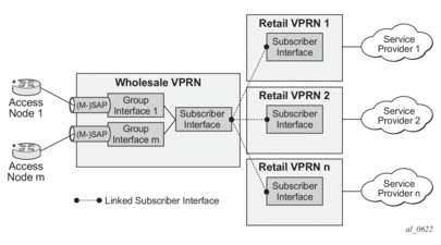
In a wholesale retail model, two subscriber interfaces must be configured and linked together: one in the wholesale VPRN and one in the retail service.
The wholesale subscriber interface defines the IP subnets and host specific configuration parameters for subscriber hosts belonging to the wholesaler. There are associated group interfaces that contain the SAPs which connect to the access nodes.
The retail subscriber interface defines the IP subnets and host specific configuration parameters for subscriber hosts belonging to the retailer. The retail subscriber interface is linked to a wholesale subscriber interface for forwarding via explicit configuration. There are no associated group interfaces.
For example:
A retail subscriber interface can be linked to a single wholesale subscriber interface and context only. Subscriber interface chaining (linking a retail subscriber interface to another retail subscriber interface) is not supported. Multiple retail subscriber interfaces belonging to different retail contexts can be associated with a single wholesale subscriber interface. When a retail subscriber interface is linked to a wholesale context, all other retail subscriber interfaces from the same retailer must be linked to the same wholesale context.
9.4.19.2.2. Configuration and Applicability
As explained in the previous section, the wholesale retail model is provisioned with the linking of a subscriber interface in a retail service to a subscriber interface in the wholesale VPRN service.
Because a retail subscriber interface does not have a group-interface context, some group-interface-specific CLI parameters such as to configure dhcp relay are made available at the retail subscriber interface level. Other CLI parameters such as to provision Radius or local user database authentication are configured at the wholesale subscriber or group interface and apply to both wholesale and retail subscriber hosts.
The DHCP lease-populate configuration is special in wholesale retail as it is configured in both wholesale and retail context. The lease-populate value in the wholesale group-interface dhcp context controls the per SAP limits while the lease-populate value configured in the retail subscriber interface dhcp context controls the limits for the retailer subscriber interface. Both limits must be satisfied before a new subscriber host can be instantiated.
The sample configurations below enable dual stack IPoE devices to connect to wholesale service VPRN 4000 and retail service VPRN 4001. Hosts connected in VPRN 4000 get their IP address assigned from RADIUS, hence the proxy server configuration. Hosts connected in VPRN 4001 get their IP address from a DHCP server, hence the DHCP relay configuration.
Only the service configurations are shown. They have to be completed with authentication policies and subscriber management configuration such as radius-server-policies, sub- and sla-profiles, and so on.
Sample configuration – Wholesale VPRN Service:
Sample configuration – Retail VPRN Service:
The wholesale retail model applies to all IPoE, PPPoE PTA, IPv4 and IPv6 host types.
The wholesale service type must be VPRN. For IPoEv4 hosts, the retail service type must be a VPRN. For all other host types, the retail service type can be IES or VPRN.
Multicast-per-host replication can be enabled without support for multi-chassis redundancy.
The wholesale retail model can be deployed in combination with managed SAPs.
Overlapping subscriber subnets and prefixes in retail VPRN services associated with the same wholesale forwarding service are supported for PPPoE (IPv4 and IPv6) and IPoEv6. This is enabled by configuring private retail subnets on the retail subscriber interface. Private retail subnets cannot be configured when multi-chassis redundancy is needed.
9.4.19.2.3. Hub-and-Spoke Forwarding
In some cases, hub-and-spoke-type forwarding is needed for the retailer’s VPRN. When the retailer expects all subscriber traffic to reach its router (for accounting, monitoring, wiretapping, and so on) normal best-hop behavior within the retailer VPRN is not desired. Any subscriber-to- subscriber traffic will be forwarded within the VPRN preventing the retailer from receiving these packets. To force all subscriber packets to the retailer network, a new type of hub-and-spoke topology is defined: “type subscriber-split-horizon”. It can be used to force all subscriber traffic (upstream) to the retailer’s network. The system requires that the operator shutdown the VPRN service to enable this flag.
With retail VPRN type configured to subscriber-split-horizon, routes learned from MBGP, IGP through a regular interface, static routes through regular interfaces and locally attached regular interface routes are considered hub routes and are used for upstream traffic forwarding. Subscriber subnets cannot be used for upstream traffic forwarding. Downstream traffic will use routes in both hub and spoke routing instances.
Figure 113 shows user-to-user traffic forwarding for both retail VPRN types: regular and subscriber-split-horizon.
Figure 113: Wholesale Retail – Hub-and-Spoke Forwarding
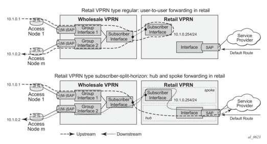
Hub-and-spoke forwarding can also be used in combination with wholesale unicast RPF (uRPF) check. The uRPF is performed on upstream traffic on spoke routes (subscriber subnets) and the forwarding uses hub routes only.
9.4.19.3. Routed Subscriber Hosts
Figure 114: Router Subscriber Hosts

A routed subscriber host associated route is a global routable subnet/prefix behind a routed CPE or Home Gateway. The routed CPE is identified in the BNG as an ESM subscriber host: QoS, accounting and anti-spoofing is enforced per CPE. The associated routes are installed in the BNG route table with next-hop pointing to the routed subscriber host’s WAN address.
Routed subscriber host associated routes are supported on IES/VPRN subscriber interfaces in a routed CO configuration. To put a SAP or MSAP in routed subscriber mode, the anti-spoof type for the SAP or MSAP must be configured to nh-mac:
There are three ways to learn about a routed subscriber host associated IPv4 route:
- Configuration for a static host
- A dynamic BGP peer
- The RADIUS [22] Framed-Route attribute
A routed subscriber host associated IPv6 route can only be learned with the RADIUS [99] Framed-IPv6-Route attribute.
9.4.19.3.1. Static Configured IPv4 Managed Route
The routes associated with a static host are populated in the routing table as “Remote Managed” routes. Up to sixteen managed routes can be configured for a static host.
To display the managed routes associated with a routed subscriber host, use following commands:
show service id service-id static-host detail
9.4.19.3.2. Static Configured IPv6 Managed Route
The routes associated with a static host are populated in the routing table as “Remote Managed” routes. Up to sixteen managed routes can be configured for a static host.
To display the managed routes associated with a routed subscriber host, use following commands:
show service id service-id static-host detail
9.4.19.3.3. Dynamic BGP Peering
Routed subscriber host associated IPv4 routes can be learned over a dynamic BGP IPv4 peer that is automatically set up when a subscriber host is instantiated. The parameters for the BGP peer are configured in a BGP peering policy or obtained in Radius VSA attributes. The subscriber-host IPv4 address is used as the BGP peer IP address. The BGP peering is torn down and the associated routes removed from the routing table as soon as the subscriber-host is removed.
Dynamic BGP peering is supported for routed subscriber hosts terminated in a VPRN service and is not supported for routed subscriber hosts terminated in an IES service. The BGP learned routes scaling is limited by the BGP scaling limits. The routes learned via a dynamic BGP peer are populated in the routing table as “Remote BGP” routes.
To display the BGP learned routes associated with a routed subscriber host, use the regular BGP commands. For example:
show router service-id bgp neighbor ip-address received-routes
An ESM dynamic BGP group must be configured in the BGP cli context of the VPRN service where the subscriber host is started:
config>service>vprn>bgp
The BGP peering policy to be used must be configured in the subscriber-mgmt CLI context:
An ESM dynamic BGP peer is established for a subscriber host if the RADIUS attribute [26-6527-55] “Alc-BGP-Policy” returned in the Access-Accept contains the name of a local configured bgp-peering-policy and if an ESM dynamic peer group is configured in the VPRN BGP context.
BGP peering parameters can be specified from multiple sources:
- Use BGP peering parameters returned in RADIUS VSA attributes
- If not available from RADIUS, use BGP peering parameters configured in the bgp-peering-policy
- If not configured in the bgp-peering-policy, use BGP peering parameters configured for the esm-dynamic-peer group
- If not configured in the esm-dynamic-peer group, use the BGP peering parameters configured in the VPRN service BGP CLI context.
- If not configured in the VPRN service BGP CLI context, use the defaults
The import and export policies to be used for the dynamic bgp peer are determined in following priority order:
- Use import/export policies returned in RADIUS VSA attributes and append policies configured in the bgp-peering-policy.
- If not available from RADIUS AND not configured in the bgp-peering-policy, use the policies configured in the esm-dynamic-peer group.
- If not configured in the esm-dynamic-peer group, use the policies configured in the VPRN service BGP CLI context.
Table 63 details the RADIUS VSA attributes that can be used to setup dynamic BGP peering.
Table 63: RADIUS VSA Attributes to Setup Dynamic BGP Peering
Attribute-ID | Attribute Name | Description |
26-6527-55 | Alc-BGP-Policy | Mandatory attribute to setup a dynamic BGP peer. References a bgp peering policy configured in the “configure subscriber-mgmt bgp-peering-policy <policy-name>” CLI context. |
26-6527-56 | Alc-BGP-Auth-Keychain | Optional. References a keychain configured in the “configure system security keychain <keychain-name> “ CLI context. |
26-6527-57 | Alc-BGP-Auth-Key | Optional. The MD5 authentication key used between BGP peers for BGP session establishment. |
26-6527-58 | Alc-BGP-Export-Policy | Optional. References a pre-configured BGP export routing policy. |
26-6527-59 | Alc-BGP-Import-Policy | Optional. References a pre-configured BGP import routing policy. |
26-6527-60 | Alc-BGP-PeerAS | Optional. Specifies the Autonomous System number for the remote peer |
9.4.19.3.4. RIP Listener
If a routed subscriber host is associated with a RIP policy, the host’s IPv4 routes can be learned over RIP. The BNG only supports RIP listener and does not support sending RIP routes to subscribers. To enable RIP for a subscriber, the subscriber must first be associated with a rip-policy. The group interface of the subscriber must also be configured as a RIP neighbor. The rip- policy can be associated to the subscriber during authentication from LUDB or via RADIUS. It can also be configured directly for static hosts. The RIP routes learned from a subscriber is removed as a subscriber is purged or shutdown from the system. RIP listening for ESM host is supported on both IES and VPRN.
To display the RIP learned routes associated with a routed subscriber host, use the regular RIP commands. For example:
The group interface must be configured in the RIP CLI context of the routed instance where the subscriber host is created:
The RIP policy is configured in the subscriber-mgmt CLI context:
A RIP neighbor is established for a subscriber host if the RADIUS attribute [26-6527-207] “Alc-RIP-Policy” is returned in the Access-Accept or in LUDB. RIP parameters such as authentication key and type can be specified in the RIP policy.
For more information about RIP, refer to the Unicast Routing Protocols Guide.
9.4.19.3.5. RADIUS: Framed-Route and Framed-IPv6-Route
RADIUS attribute [22] Framed-Route can be specified in a RADIUS Access-Accept message to associate an IPv4 route with an IPv4 routed subscriber host and Radius attribute [99] Framed-IPv6-Route can be used to associate an IPv6 route with an IPv6 routed subscriber wan host (DHCPv6 IA-NA or SLAAC). These routes are populated in the routing table as “Remote Managed” routes. Up to sixteen managed routes can be installed for a routed subscriber host; this corresponds with up to sixteen Framed-Routes and sixteen Framed-IPv6-Routes for a dual stack routed subscriber. Framed-IPv6-Routes cannot be associated with a Prefix Delegation host (DHCP IA-PD).
The Framed-Route and Framed-IPv6-Route attributes should be formatted as:
"<ip-prefix>[/<prefix-length>] <space> <gateway-address> [<space> <metric>] [<space> tag <space> <tag-value>] [<space> pref <space> <preference-value>]”
where:
<space> — is a white space or blank character.
<ip-prefix>[/prefix-length] — is the managed route to be associated with the routed subscriber host. The prefix-length is optional for an IPv4 managed route. When not specified, a class-full class A,B or C subnet is assumed. The prefix-length is mandatory for an IPv6 managed route.
<gateway-address> — must be the routed subscriber host IP address. “0.0.0.0” is automatically interpreted as the host IPv4 address for managed IPv4 routes.
“::” and “0:0:0:0:0:0:0:0” are automatically interpreted as the wan-host IPv6 address for managed IPv6 routes.
[<metric>] — Optional. Installed in the routing table as the metric of the managed route. If not specified, metric zero is used. Value = [0.. 65535].
[tag <tag-value>] — Optional. The managed route will be tagged for use in routing policies. If not specified, or tag-value = 0, then the route is not tagged. Value = [0..4294967295].
[pref <preference-value>] — Optional. Installed in the routing table as protocol preference for this managed route. If not specified, preference zero is used. Value = [0..255].
If the optional metrics (metric, tag and/or preference) are specified in a wrong format or with out of range values, then the defaults are used for all metrics: metric=0, no tag and preference=0. No event is logged.
If the Framed-Route or Framed-IPv6-Route is invalid (for example because the gateway address specified does not match the host wan IP address or because the host bits are not zero) then the routed subscriber host is instantiated without the ill defined managed route. An event is logged in this case.
Equal Cost Multi-Path (ECMP) is supported for Framed-Route and Framed-IPv6-Route:
The maximum number of equal cost paths in a routing instance is configured with:
If an identical managed route is associated with different routed subscriber hosts in the context of the same IES/VPRN service, up to <max-ecmp-routes> managed routes are installed in the routing table. Candidate ECMP Framed-Routes/Framed-IPv6-Routes have:
- Identical prefix
- Equal lowest preference
- Equal lowest metric
A tie breaker determines if more candidate ECMP Framed-Routes/Framed-IPv6-Routes are available than the configured <max-ecmp-routes> is: Lowest ip next-hop.
Other identical managed routes are shadowed and an event is logged.
Note that Candidate ECMP Framed-Routes/Framed-IPv6-Routes can belong to hosts of the same or different subscriber.
Valid Framed-Routes and Framed-IPv6-Routes are persistent (stored in the persistency file for recovery after reboot) and synchronized in a Multi-Chassis Redundancy configuration.
RADIUS-learned Framed-Route/Framed-IPv6-Route and static host associated managed routes that are installed in the routing table can be identified in routing policies for redistribution as protocol “managed”.
To display the managed routes associated with a routed subscriber host, use following commands:
show service id service-id dhcp lease-state detail
show service id service-id dhcp6 lease-state detail
show service id service-id slaac host detail
show service id service-id ppp session detail
show service id service-id pppoe session detail
show service id service-id arp-host detail
Valid RADIUS-learned managed routes can be included in RADIUS accounting messages with the following configuration:
Associated managed routes for an instantiated routed subscriber host are included in RADIUS accounting messages independent of the state of the managed route (Installed, Shadowed, HostInactive, etc.)
For a PPP session, when a Framed-Route or Framed-IPv6-Route is available while the corresponding routed subscriber host is not yet instantiated, the managed route is in the state “notYetInstalled” and will not be included in RADIUS accounting messages.
9.4.19.3.6. GRT Lookup and Routed CO in a VPRN
GRT lookup allows routing from a VPRN to the GRT, and GRT leaking allows routing from the GRT to a VPRN. These features are particularly useful when VPRNs require routing to the Internet and the GRT already contains the Internet routing table. Wholesale/retail VPRNs and the routed CO VPRN have both GRT lookup and GRT leaking support.
The config>service>vprn>grt-lookup>export-grt command exports subscriber-related routes and protocols to the GRT. This allows traffic arriving from the network port to be routed downstream to the subscriber. The following configurations are supported in the downstream direction.
- For an IPv4 numbered subscriber interface inside a routed CO VPRN, an IPv4 subscriber subnet can be exported as a policy using the config>service>vprn>grp-lookup>export-grt command, where the policy is configured with the config>router>policy-options>policy-statement command.For an IPv6 numbered subscriber interface inside a routed CO VPRN, an IPv6 subscriber subnet/prefix can be exported as a policy using the config>service>vprn>grp-lookup>export-grt command, where the policy is configured with the config>router>policy-options>policy-statement command.
- Subscriber-related protocols (managed routes and subscriber management routes) inside a routed CO VPRN can be exported to the GRT.
- For an IPv4 unnumbered subscriber interface inside a routed CO VPRN, subscriber host /32 routes are exported individually to the GRT using the “sub-mgmt” protocol.
- For an IPv6 unnumbered subscriber interface inside a routed CO VPRN, subscriber host /128 routes and/or prefixes are exported individually to the GRT using the “sub-mgmt” protocol.
- The retail VPRN supports all items listed above for a routed CO VPRN (exporting subscriber routes and protocols to the GRT via the config>service>vprn>grp-lookup>export-grt command). The retail VPRN does not export host routes by default. Therefore, the export-host-routes command may be required for a retail VPRN unnumbered subscriber interface.
- The wholesale VPRN supports all items listed above for a routed CO VPRN (exporting subscriber routes and protocols to the GRT via a route policy). However, retail-related routes that appear in the FIB of the wholesale VPRNs, cannot be exported. Retail-related routes must be exported individually within the VPRN to the GRT. This provides control over which retail VPRNs route to the GRT.
GRT lookup supports traffic from the subscriber to be routed upstream to the GRT. The following configurations are supported in an upstream direction:
- routed CO VPRN and grt-lookup
- wholesale VPRN and grt-lookup
- retail VPRN and grt-lookup
Not Supported
- SRRP setup in routed CO VPRN
- SRRP setup in wholesale/retail VPRN
9.4.20. Dual Homing
All residential networks are based on two models: Layer 2 CO and Layer 3 CO. Dual homing methods for Layer 2 CO include MC-LAG and MC-Ring. Dual homing for Layer 3 CO is based on SRRP and can be done in ring-topologies (l3-mc-ring or with directly attached nodes. All methods use multi-chassis synchronization protocol to sync subscriber state.
9.4.20.1. Dual Homing to Two PEs (Redundant-Pair Nodes) in Triple Play Aggregation
Figure 115: Dual-Homing to Two PEs
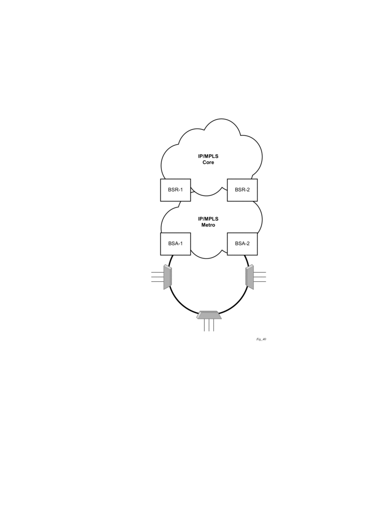
Figure 115 depicts dual-homing to two different PE nodes. The actual architecture can be based on a single DSLAM having two connections to two different PEs (using MC-LAG) or ring of DSLAMs dual-connected to redundant pair of PEs.
Similarly to previous configuration, both aggregation models (VLAN-per-subscriber or VLAN-per-service) are applicable.
Configurations include:
- Loop resolution and failure recovery — Can be based on MC-LAG or mVPLS.
- DHCP-lease-state persistency — Stores all required information to recover from node failure.
- DHCP-lease-state synchronization — A mechanism to synchronize the DHCP lease-state between two PE nodes in the scope of redundancy groups (a group of SAPs used for dual homing).
- IGMP snooping state synchronization — Similarly to DHCP lease-state synchronization, IGMP snooping state is synchronized to ensure fast switchover between PE nodes. In a VPLS network, a BTV stream is typically available in all PE nodes (the ring interconnecting all PEs with Mcast routers is typically used) so the switch over can be purely driven by RSTP or MC-LAG.
- ARP reply agent responses — The ARP reply agent can response to ARP requests addressing a host behind the given SAP if the SAP is in a forwarding state. This prevents the FDB table in the VPLS from being “poisoned” by ARP responses generated by the node with a SAP in a blocking state (see Figure 116).
Figure 116 shows a typical configuration of network model based on Layer 2 CO model. Individual rings of access nodes are aggregated at BSA level in one (or multiple) VPLS services. At higher aggregation levels (the BSR), individual BSAs are connected to Layer 3 interfaces (IES or VPRN) by spoke SDP termination. Every Layer 3 interface at BSR level aggregates all subscribers in one subnet.
Figure 116: Layer 2 CO Dual Homing - Network Diagram
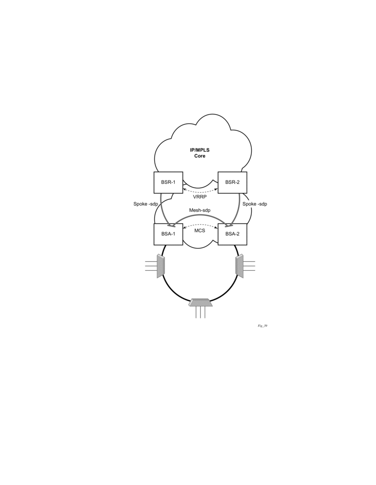
Typically, BTV service distribution is implemented in a separate VPLS service with a separate SAP per access-node. This extra VPLS is not explicitly indicated in Figure 116 (and subsequent figures) but the descriptions refer to its presence.
From a configuration point of view in this model, it is assumed that all subscriber management features are enabled at the BSA level and that synchronization of the information (using multi-chassis synchronization) is configured between redundant pair nodes (BSA-1 and BSA-2 shown in Layer 2 CO Dual Homing - Network Diagram). The multi-chassis synchronization connection is used only for synchronizing active subscriber host database and will operate independently from dual-homing connectivity control. At the BSR level, there are no subscriber management features enabled.
The operation of redundancy at the BSR level through VRRP is the same as dual homing based on MC-LAG. The operation of dual homing at BSA level is based on two mechanisms. Ring control connection between two BSAs have two components, in-band and out-of-band communication. With in-band communication, BFD session between BSA-1 and BSA-2 running through the access ring and using dedicated IES/VPRN interface configured on both nodes. This connection uses a separate VLAN throughout the ring. The access nodes provides transparent bridging for this VLAN. The BFD session is used to continuously verify the integrity of the ring and to detect a failure somewhere in the ring.
With out-of-band communication, the communication channel is used by BSA nodes to exchange information about the reachability of individual access nodes as well as basic configurations in order to verify the consistency of the ring. The configuration information is synchronized through multi-chassis synchronization and therefore it is mandatory to enable multi-chassis synchronization between two nodes using the multi-chassis-ring concept.
In addition, the communication channel used by MC-LAG or MC-APS control protocol is used to exchange some event information. The use of this channel is transparent to the user.
Ring node connectivity check continuously checks the reachability of individual access nodes in the ring. The session carrying the connection is conducted on separate VLAN, typically common for all access nodes. SHCV causes no interoperability problems.
9.4.20.2. Steady-State Operation of Dual-homed Ring
Figure 117 illustrates the operation of the dual-homed ring. The steady state is achieved when both nodes are configured in a consistent way and the peering relation is up. The multi-chassis ring must be provisioned consistently between two nodes.
In-Band Ring Control Connection (IB-RCC) is in operational UP state. Note that this connection is set up using a bi-directional forwarding session between IP interfaces on BSA-1 and BSA-2.
Figure 117: Dual Homing Ring Under Steady-State Condition
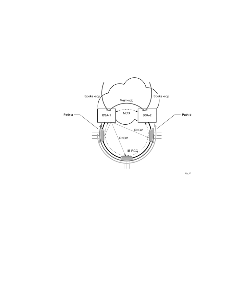
In Figure 117, the ring is fully closed and every access node has two possible paths towards the VPLS core. Figure 117 refers to these as path-a and path-b. In order to avoid the loop created by the ring, only one of the paths can be used by any given ring node for any given VLAN. The assignment of the individual VLANs to path-a or path-b, respectively, has to be provisioned on both BSAs.
The selection of the BSA master for both paths will be based on the IP address of the interface used for IB-RCC communication (bi-directional forwarding session). The BSA with the lower IP address of the interface used as IB-RCC channel will become master for ring nodes and their respective VLANs assigned to path-a. The master of path-b will be other BSA.
In this example, each path in the ring has a master and standby BSA. The functionality of both devices in steady state are as follows:
In the master BSA:
- All SAPs that belong to the path where the given BSA is a master, are operationally UP and all FDB entries of subscriber hosts associated with these SAPs point to their respective SAPs.
- The master of a path performs periodical Ring Node Connectivity Verification (RNCV) check to all ring nodes.
- In case of a RNCV failure, the respective alarm will be raised. Note that the loss of RNCV to the given ring node does not trigger any switchover action even if the other BSA appears to have the connection to that ring node. As long as the BFD session is up, the ring is considered closed and the master/standby behavior is driven solely by provisioning of the individual paths.
- The ARP reply agent replies to ARP requests addressing subscriber hosts where the BSA master.
In the standby BSA:
All SAPs that belong to a BSA’s path, the standby will be operationally down and all FDB entries of subscriber hosts associated with those SAPs will be pointing towards SDP connecting to master BSA (also called a shunt SDP).
In both BSAs:
- The information on individual paths assignment is exchanged between both BSAs through multi-chassis synchronization communication channel and conflicting SAPs (being assigned to different paths on both BSA nodes) will be forced to path-a (the default behavior).
- For IGMP snooping, the corresponding multi-chassis IDs are targeting all subscriber-facing SAPs on both nodes. On the standby BSA node, the corresponding SAPs are in an operationally down state to prevent the MC traffic be injected on the ring twice.
9.4.20.3. Broken-Ring Operation and the Transition to this State
Figure 118 illustrates the model with a broken ring (link failure or ring node failure). This state is reached in following conditions:
- Both nodes are configured similarly.
- Peering is up.
- The multi-chassis ring is provisioned similarly between two nodes
- IB-RCC is operationally down.
In this scenario, every ring node has only one access path towards the VPLS core and hence, the Path-a and Path-b notion has no meaning in this situation.
Functionally, both BSAs are now the master for the reachable ring nodes and will take action as described in Steady-State Operation of Dual-homed Ring. For all hosts behind the unreachable ring nodes, the corresponding subscriber host FDB entries point to the shunt SDP.
Figure 118: Broken Ring State
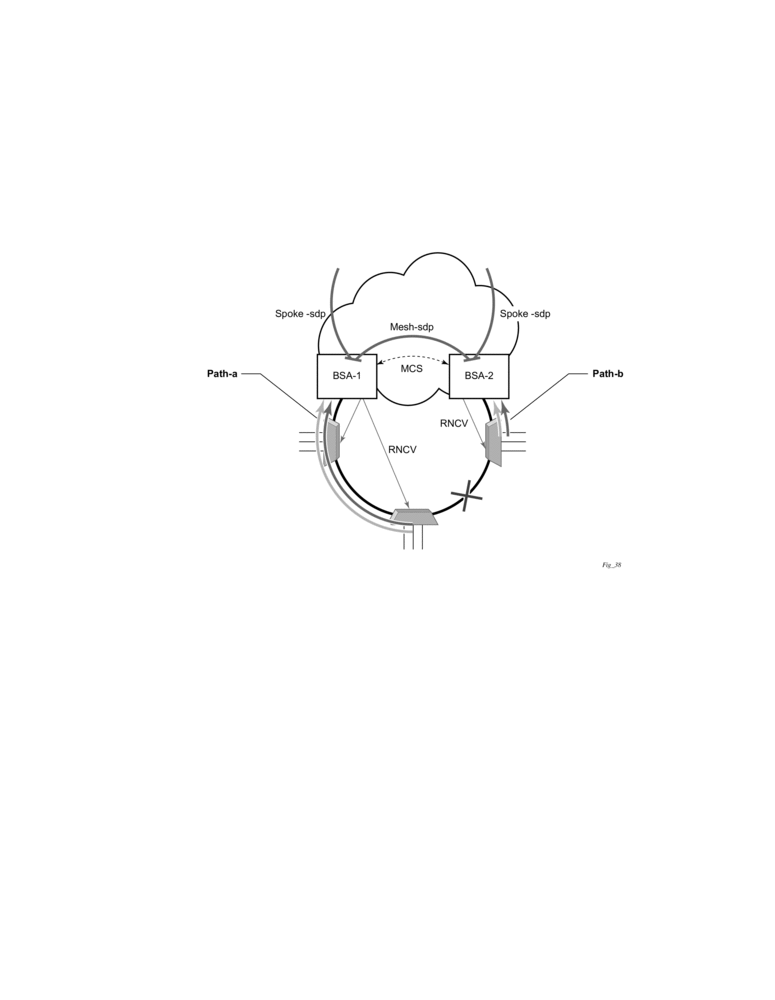
The mapping of individual subscriber hosts into the individual ring nodes is complicated, especially in the VLAN-per-service model where a single SAP can represent all nodes on the ring. In this case, a given BSA can have subscriber hosts associated with the given SAP that are behind reachable ring nodes as well as subscriber hosts behind un-reachable ring nodes. This means that the given SAP cannot be placed in an operationally down state (as in a closed ring state), but rather, selectively re-direct unreachable subscriber states to the shunt SDP.
All SAPs remain in an operationally up state as long as the ring remains broken. This mainly applies for BTV SAPs that do not have any subscriber hosts associated with and do not belong to any particular ring node.
In order to make the mapping of the subscriber-hosts on the given ring node automatically provisioned, the ring node identity will be extracted during subscriber authentication process from RADIUS or from a Python script. The subscriber hosts which are mapped to non-existing ring node will remain attached to the SAP.
At the time both BSA detect the break in IB-RCC communication (if BFD session goes down) following actions are taken:
- Both nodes trigger a RNCV check towards all ring nodes. The node, which receives the reply first, will assume a master functionality and will inform the other BSA through an out-of-band channel. This way, the other node can immediately take actions related to the standby functionality without waiting for an RNCV timeout. Even if the other node receives an RNCV response from the given ring node later, the master functionality remains with the node the received the response first.
- After assuming the master functionality for hosts associated with the given SAP(s), the node will send out FIB population messages to ensure that new path towards the VPLS core is established. The FIB population messages are sourced from the MAC address of the default gateway used by all subscriber hosts (such as the VRRP MAC address) which is provisioned at the service level.
9.4.20.4. Transition from Broken to Closed Ring State
By its definition, the multi-chassis ring operates in a revertive mode. This means that whenever the ring connectivity is restored, the BSA with lower IP address in the IB-RCC communication channel will become master of the path-a and vice versa for path-b.
After restoration of BFD session, the master functionality, as described in Steady-State Operation of Dual-homed Ring, is assumed by respective BSAs. The FDB tables are updated according to the master/standby role of the given BSA and FDB population messages is sent accordingly.
9.4.20.5. Provisioning Aspects and Error Cases
The multi-chassis ring can operate only if both nodes similarly configured. The peering relation must be configured and both nodes must be reachable at IP level. The multi-chassis ring with a corresponding sync-tag as a ring-name identifying a local port ID must be provision on both nodes. And, BFD session and corresponding interfaces needs to be configured in a consistent way.
In case the multi-chassis rings are not provisioned consistently, the ring will not become operational and the SAP managed by it will be in operationally up state on both nodes.
The assignment of individual SAPs to path-a and path-b is controlled by configuration of VLAN ranges according to the following rules:
- By default, all SAPs (and hence all VLANs on the given port) are assigned to path-a.
- An explicit statement defining the given VLAN range assigns all SAPs falling into this range to the path-b.
- An explicit statement defining the given VLAN range defines all SAPs that are excluded from the multi-chassis ring control.
- In case of a conflict in the configuration of VLAN ranges between two redundant nodes is detected, all SAPs falling into the “conflict-range” will be assigned to path-a, on both nodes regardless the local configuration.
- For QinQ-encapsulated ports the VLAN range refers to the outer VLAN.
9.4.20.6. Dual Homing to Two BSR Nodes
Figure 119 depicts a single DSLAM dual-homed to two BSRs.
Figure 119: Low
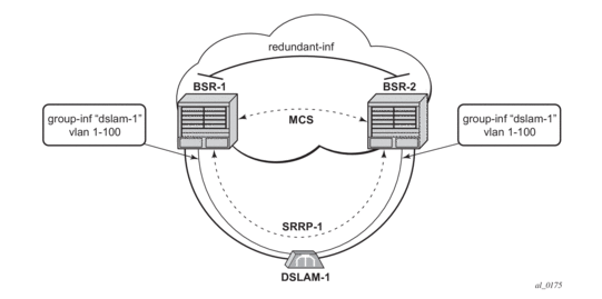
In order to provide dual-homing in the context of subscriber interfaces, the following items must be configured on both BSRs:
- Group interface (dslam-1) with corresponding SAPs (vlan 1-100)
- SRRP instance controlling given group interface
- Redundant interface between BSRs to provide “shunt” connectivity
- MCS connection to provide synchronization of dynamic subscriber-host entries
During the operation, BSR-1 and BSR-2 will resolve master-backup relation and populate respective FIBs in such a way that at master side, subscriber-host entries point to corresponding group-interface while at the back-up side, subscriber-host entries point to the redundant interface. Note that the logical operation of the ring in the Layer 3 CO model is driven by SRRP. For more details on SRRP operation, refer to Subscriber Routed Redundancy Protocol (SRRP).
9.4.20.7. MC Services
The typical implementation of MC services at the network level is shown in Figure 120.
Figure 120: MC Services in a Layer 3-Ring Topology (a)

The IGMP is used to register joins and leaves of the user. IGMP messaging between BSRs is used to determine which router performs the querier role (BSR2 in Figure 120). PIM is used to determine which router will be the designated router and the router that sends MC streams on the ring.
The access nodes have IGMP snooping enabled and from IGMP messaging between BSR, they are aware which router is the querier. In the most generic case, IGMP snooping agents (in access nodes) send the IGMP-joins messages only to IGMP-querier. The synchronization of the IGMP entries can be then be performed through MCS. In some cases, access nodes can be configured in such a way that both ring ports are considered as m-router ports and IGMP joins are sent in both directions.
All of the above is a steady state operation which is transparent to the topology used in a Layer 2 domain.
A ring-broken state is shown in Figure 121.
In this case, IGMP and PIM messaging between BSRs is broken and both router assume role of querier and role of designated router. By the virtue of ring topology, both routers will see only IGMP joins/leaves generated by host attached to a particular “half” of the ring. This means that both routers will have “different” view on dynamic IGMP state.
Figure 121: MC Services on a Layer 3-Ring Topology (b)

In principle, MCS could be used to synchronize both routers, but in case of a Layer 2 ring, the implementation sends all IGMP messages to a “ring-master: which then performs IGMP processing and consequently, MCS sync. As a result, any race conditions are avoided.
Another ring-specific aspect is related to ring healing. The ring continuity check is driven by BFD which then drives SRRP and PIM messaging. BFD is optimized for fast detection of ring-down events while ring-up events are announced more slowly. There is a time window when routers are not aware that the ring is recovered. In the case of MC, this means traffic will be duplicated on the ring.
To avoid this, the implementation of BFD provides a “raw mode” which provides visibility on “ring-up” events. The protocols, such as SRRP and PIM, use this raw mode rather than the BFD API.
9.4.20.8. Routed CO Dual Homing
Routed CO dual homing is a solution that allows seamless failover between nodes for all models of routed CO. In the dual homed environment, only one node will forward downstream traffic to a given subscriber at a time. Dual homing involves several components:
- Redundant Interface — This is used to shunt traffic to the active node for a given subscriber for downstream traffic.
- SRRP — This is used to monitor the state of connectivity to the DSLAM. Refer to the SRRP section for more detail.
- MCS — This is used to exchange subscriber host and SRRP information between the dual homed nodes.
Routed CO dual homing can be configured for both wholesaling models. Dual homing is configured by creating a redundant interface that is associated with the protected group interfaces. The failure detection mechanism can be VRRP. If VRRP is used, each node monitors the VRRP state to determine the priority of its own interface.
Dual homing is used to aggregate a large number of subscribers in order to support a redundancy mechanism that will allow a seamless failover between nodes. Because of the Layer 3 nature of the model, forwarding is performed for the full subscriber subnet.
9.4.20.8.1. Redundant Interfaces
In dual homing, a redundant interface must be created. A redundant interface is a Layer 3 spoke SDP-based interface that allows delivery of packets between the two nodes. The redundant interface is required to allow a node with a failed link to deliver packets destined to subscribers behind that link to the redundant node. Since subscriber subnets can span multiple ports it is not possible to stop advertising the subnet, thus, without this interface the node would black hole.
The redundant interface is associated with one or more group interfaces. An interface in backup state will use the redundant interface to send traffic to the active interface (in the active node). The SAP structure under the group interface must be the same on both nodes as the synchronization of subscriber information is enabled on a group interface basis. Traffic can be forwarded through the redundant interface during normal operation even when there are no failed paths. See Figure 122.
9.4.20.8.2. SRRP in Dual Homing
Subscriber Router Redundancy Protocol (SRRP) allows two separate connections to a DSLAM to operate in an active/standby fashion similar to how VRRP interfaces operate. Since the SRRP state is associated with the group-interface, multiple group-interfaces may be created for a given port such that some of the SAPs will be active in one node and others active on the other node. While each SRRP pair is still allowed to be active/backup, the described configuration is allowed for load balancing between the nodes. Note that in a failure scenario subscriber bandwidth will be affected. For more information about SRRP, refer to Subscriber Routed Redundancy Protocol (SRRP).
If SRRP is configured before the redundant interface is up, and in backup state the router will forward packets to the access node via the backup interface but will not use the gateway MAC address. This applies to failures in the redundant interface as well. If the redundant interface exists and up the router will send downstream packets to the redundant interface and will not use the backup group interface.
In a dual homing architecture the nodes must be configured with SRRP to support redundant paths to the access node. The nodes must also be configured to synchronize subscriber data and IGMP state. To facilitate data forwarding between the nodes in case some of the ports in a given subscriber subnet are affected a redundant interface must be created and configured with a spoke. The redundant interface is associated with one or more group interfaces.
The service IDs for both the wholesale VPRN and the retailer VPRN must be the same in both nodes.
An interface in backup state will use the redundant interface to send traffic to the active interface (in the active node). The SAP structure under the group interface must be the same on both nodes as the synchronization of subscriber information is enabled on a group interface basis.
SRRP is associated a group-interface. Multiple group-interfaces can be created for a given port such that some of the SAPs will be active in one node and others active on the other node. While every SRRP pair is still allowed to be active/backup the described configuration will allow for load balancing between the nodes. Note that in a failure scenario subscriber bandwidth will be affected.
Figure 122: Dual Homing Example
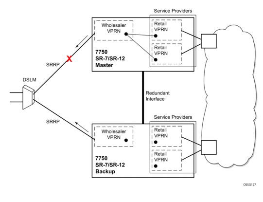
9.4.20.8.3. Synchronization
To establish subscriber state the nodes must synchronize subscriber information. Refer to the Basic Configuration Guide for multi-chassis synchronization configuration information. The operator must complete the configuration and the system must have data synchronized before the backup node may deliver downstream packets to the subscriber.
If dual homing is used with regular interfaces that run IGMP the nodes must be configured to synchronize the Layer 3 IGMP state.
The service IDs for both the wholesale VPRN and the retailer VPRN must be the same in both nodes.
9.4.20.8.4. Wholesale-Retail Multi-Chassis Redundancy
Multi-Chassis Redundancy for a retail service is enabled with the SRRP and redundant interface configuration on the wholesale group-interface parented by the forwarding subscriber interface. The Multi-Chassis state (active or standby) of the retail subscriber host is determined from the SRRP state (master / non-master) of the group-interface that parents the SAP of the retail subscriber host. The retail service id must be equal on both nodes.
Sample wholesale service configuration:
Sample retail service configuration:
Overlapping addresses in retail subscriber interfaces (enabled with private-retail-subnets) cannot be used in combination with multi-chassis redundancy. This is because retail subscriber subnets and prefixes leaked in the wholesale service are needed to forward downstream shunted traffic over the redundant interface. For the same reason, retail unnumbered host routes must be leaked in the wholesale service:
- The address of an IPv4 unnumbered subscriber host (enabled with unnumbered ip-int-name | ip-address or allow-unmatching-subnets on the retail subscriber interface) is not contained in the subnets configured on the retail subscriber interface. The export of the IPv4 retail subscriber host routes to the wholesale service must be explicitly enabled with the export-host-routes command:
- The address of an IPv6 unnumbered subscriber host (enabled with ipv6 allow-unmatching-prefixes on the retail subscriber interface) is not contained in the IPv6 prefixes configured on the retail subscriber interface. IPv6 retail subscriber host routes are automatically exported to the wholesale service.
Downstream traffic arriving on an SRRP non-master node must be shunted over the redundant interface. Downstream traffic shunting can be reduced by advertising the retail subscriber subnets and prefixes from the master SRRP node with a more favorable metric using routing policies. To make retail subscriber subnets and prefixes SRRP state-aware, they have to be configured to track an SRRP instance that is active on a group interface of the connected wholesale subscriber interface:
Multi-Chassis Redundancy is supported for IPoE (IPv4 and IPv6) and PPPoE (IPv4 and IPv6) retail subscriber hosts and sessions.
9.4.20.9. SRRP and Multi-Chassis Synchronization
In order to take full advantage of SRRP resiliency and diagnostic capabilities, the SRRP instance will be tied to a MCS peering that terminates on the redundant node. Once the peering is associated with the SRRP instance, MCS will synchronize the local information about the SRRP instance with the neighbor router. MCS automatically derives the MCS key for the SRRP instance based on the SRRP instance ID. An SRRP instance ID of 1 would appear in the MCS peering database with a MCS-key srrp-0000000001.
The SRRP instance information stored and sent to the neighbor router consists of:
- The SRRP instance MCS key
- Containing service type and ID
- Containing subscriber IP interface name
- Subscriber subnet information
- Containing group IP interface information
- The SRRP group IP interface redundant IP interface name, IP address and mask
- The SRRP advertisement message SAP
- The local system IP address (SRRP advertisement message source IP address)
- The group IP interface MAC address
- The SRRP gateway MAC address
- The SRRP instance administration state (up/down)
- The SRRP instance operational state (disabled/becoming-backup/backup/becoming-master/ master)
- The current SRRP priority
- Remote redundant IP interface availability (available/unavailable)
- Local receive SRRP advertisement SAP availability (available/unavailable)
9.4.20.10. Dual Homing and ANCP
The routers provide a feature related to exchange of control information between DSLAM and BRAS (BSA is described in this model). This exchange of information is implemented by in-band control connection between DSLAM and BSA, also referred to as ANCP connection.
In case of dual homing, two separate connections will be set. As a consequence, there is no need to provide synchronization of ANCP state. Instead every node of the redundant-pair obtains this information from the DSLAM and creates corresponding an ANCP state independently.
9.4.21. SRRP Enhancement
The SRRP enhancements addressed in this section is to reduce the need for redundant-interface between the pair of redundant nodes without sacrificing the subnet aggregation on the back-end.
Redundant BNG nodes are not always collocated. This means that the logical link associated with the redundant (shunt) interfaces is taking the uplink path thus wasting valuable bandwidth (downstream traffic that arrives to the Standby node is routed via uplinks for the second time over to the Master node).
To meet the requirement to reduce the existence of shunted traffic only to the short transitioning period between SRRP switchovers while the routing on the network side is converging, the following was required (referring to Figure 123):
- Share IP subnets over multiple SRRP instances. This is not mandatory, but it would helps to load balance traffic over the two nodes. For example, IP subnets 10 and 11 can be shared over SRRP instances 10 and 20 on node 1, and the IP subnet 12 can be associated with the SRRP instance 30 on node 2.
- SRRP aware routing – this allows to dynamically increase routing metric on the IP subnets advertised from the Master SRRP node in comparison to the Standby SRRP node. It also allows to advertise/withdraw routes from a routing protocol based on the SRRP state. In this fashion, downstream traffic is routed in a predictable manner towards the Master SRRP node.
- SRRP Fate Sharing for SRRP instances 10 and 11. This ensures congruency of SRRP states on the same node. This is a necessary step towards SRRP aware routing.
Figure 123: IP Subnet Per SRRP Master Group
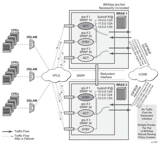
9.4.21.1. SRRP Fate Sharing
SRRP Fate Sharing is a concept in which a group of SRRP instances track a single operational-object comprised of SRRP messaging SAPs. The SRRP instances behave as one (in the single failure case) with regards to SRRP mastership. The group of SRRP instances that are sharing fate on a paired node are referred as a Fate Sharing Group (FSG).
Transition of a single messaging SAP within the FSG into a DOWN state forces the SRRP instance on top of it into the INIT state. Consequently, all other SRRP instances within the same FSG transitions into a Backup state. In other words, SRRP instances within the FSG all share the same fate as the failed SRRP instance as shown in Figure 124. SRRP Fate Sharing provides optimal protection in the context of a single failure in the network.
Figure 124: FSG -— Single Network Failure
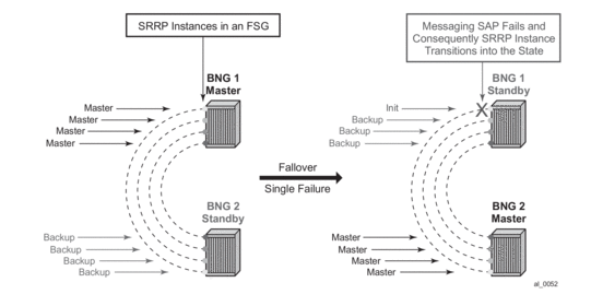
In the case of multiple network failures, the concept of the FSG breaks as there is a possibility that a ‘FSG’ contains SRRP instances that are in any of the three possible SRRP states: Master, Backup, or Init. This Fate Sharing feature may not provide optimal protection when there are multiple network failures distributed over both redundant nodes.
Figure 125: Multiple Network Failures
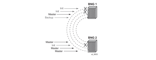
The whereabouts of the failure in the network path that SRRP is designed to monitor are not always clearly reflected through SRRP states. For example, if the network failure is somewhere in the aggregation network beyond the direct reach of our BNG, SRRP assumes Mastership on both BNG nodes. This is a faulty condition and the reason why solely monitoring of the SRRP states is not enough to protect against failures. On the other hand, the SRRP messaging SAP states are more indicative of the network failure since they can be tied into Eth-OAM.
Once a single network failure is detected and as a result an SRRP instance transitions into a non-Master state, the remaining SRRP instances in the FSG are forced into a Backup state. This is achieved by changing the priority of each individual SRRP instance in the FSG.
In the case of simultaneous multiple failures (multiple ports fail at the same time), it is possible that the SRRP instances within the FSG settle in any of the three possible SRRP states: Master, Backup, or Init. In such scenario shunted traffic will ensue.
In the premise of SRRP Fate Sharing, the network failure will be reflected in the operational state of the messaging SAP over which SRRP runs. This will certainly be the case if the failure is localized to the BNG (somewhere on the directly connected link). In the case of non-localized failure (beyond the direct reach of the BNG node), Eth-OAM might be needed in to detect the remote end failure and consequently bring the SAP operationally into a DOWN state.
Once the single network failure is detected, all instance within the FSG transitions into a non-Master state.
If there are no failures in the network, all SAPs are UP and SRRP instances within the FSG are in a homogeneous and deterministic state based on their configured priorities.
Figure 126: SRRP Fate Sharing
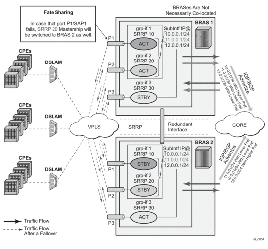
Failure Detection in a Fate Sharing Group
- Dual homing over directly connected ports. No Eth-OAM is needed, AN is directly connected to the BNG.
Figure 127: Scenario 1
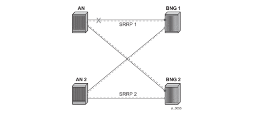
- Dual homing with aggregation network - aggregation network has no redundancy between Layer 2 switches (STP). To determine whereabouts of failure at point 1 in the figure below, Eth-OAM is needed.
Figure 128: Scenario 2
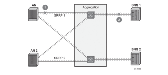
- Dual homing with aggregation network - aggregation network with redundancy between Layer 2 switches (STP). No Eth-OAM is needed in this case for successful operation. However, the failure detection is based on the failure of the directly attached ports.
Figure 129: Scenario 3
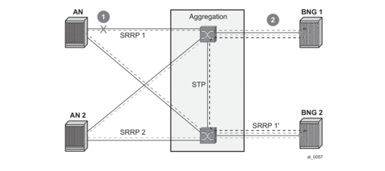
- Single homing with aggregation network. In this case, SRRP can protect only against direct failures. Any remote failure leaves a part of the network isolated from the subscriber point of view.
Figure 130: Scenario 4
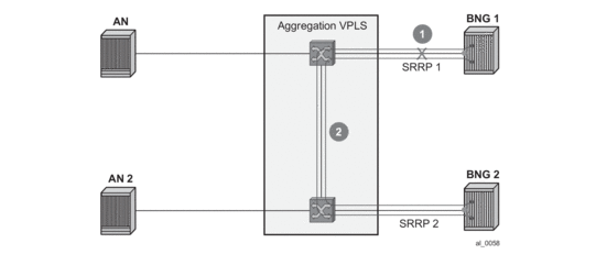
9.4.21.2. Fate Sharing Algorithm
Fate Sharing Algorithm (FSG) is relaying on tracking the state of messaging SAPs over which SRRP instances run. An SRRP instance with the messaging SAP operationally DOWN will transition into the Init state.
The transitioning of any messaging SAP in a FSG into an UP/DOWN state will trigger SRRP priority adjustment within the FSG. The SRRP priorities should be chosen carefully to achieve the desired behavior. They are modified dynamically as the SAP states change. The range in which SRRP priorities can be modified is from 1 to the SRRP priority that is initially configured under the SRRP node. Here are some general guidelines for choosing SRRP priorities in a FSG:
- Initially configured SRRP priorities for all SRRP instance within the FSG within the node should be the same.
- Initially configured SRRP priorities should be different between pairing FSGs. For example, SRRP instances in the BNG node A within an FSG will all have the same SRRP priority ‘X’, while corresponding SRRP instances on the paired node within corresponding FSG will all have SRRP priority ‘Y’. This ensures that SRRP mastership is clearly defined between the two BNG nodes. Note that this step is not mandatory as SRRP will naturally break the Mastership tie in the case that all SRRP priorities are the same. However, following this step may provide a clearer view from an operational perspective.
- The priority-step used for dynamic SRRP priority adjustment must be greater than the difference in initially configured SRRP priorities between two BNG nodes. This ensures that a single failure event triggers the SRRP switchover. Otherwise, if the dynamically lowered SRRP priority is still greater than the one from the SRRP peer, the switchover would not be triggered. Therefore, the fate sharing concept would not function as intended.
- Initially configured SRRP priority of each SRRP instance should be greater than the (anticipated) number of SRRP instances in a FSG multiplied by the SRRP priority-step. This ensures that the dynamically priority never tries to go below 1. There is a code check that prevents SRRP priority going below 1. Nonetheless, it is recommended not to get into a situation where this needs to be enforced in the code.
Note: The priorities will never be less than 1 or greater than initially configured SRRP priority.
Example scenarios:
Assume 3 SRRP instances in a FSG. The SRRP instances in the FSG-1 on BNG 1 have the priority of 100, while the SRRP instances in the FSG-2 on BNG 2 have the priority of 95. The priority-step is 6. The SRRP instances and underlying messaging SAPs will be referred as SRRP 1, 2, 3 and SAP 1,2,3, respectively.
Initialization:
Scenario 1 – all SAPs are operationally UP.
BNG 1 boots up and all messaging SAPs transition into the UP state. When the first SRRP instance in FSG-1 comes up, it looks under the FSG to finds out how many messaging SAPs are operationally UP. Since all messaging SAPs are operationally UP, this first SRRP instance assumes its initially configured priority of 100. The other two SRRP instances in the same FSG follows the same sequence of events.
BNG 2 follows the same flow of events. As a result, BNG 1 assumes mastership over BNG 1 for all SRRP instances within the corresponding FSG.
Scenario 2 – messaging SAP 1 is operationally DOWN on BNG 1, the rest of the messaging SAPS are operationally UP.
SRRP 2 and 3, during the initialization, pick up SRRP priority of 94 (100 – 1*priority-step).
On BNG 2, all messaging SAPs are UP and consequently all SRRP instances within the FSG on BNG 2 have SRRP priority of 95. The SRRP instances on BNG 2 assumes Mastership.
Scenario 3 – Continuing from scenario 2, the SAP 1 on BNG 1 transitions into the UP state. SRRP priority of each SRRP instance in FSG-1 is increased by 6, bringing it to 100, enough to assume Mastership.
Adding a New Instance into an FSG
To introduce minimal network disruption, first create messaging SAPs in both BNG nodes and ensure that both SAPs are operationally UP. Then a new SRRP 4 instance should be created on both BNG nodes. The next step would be to include this new messaging SAP into a SAP monitoring group. And finally, the SRRP-4 is added into the FSG (1 and 2). This triggers the recalculation of SRRP priorities for the existing FSG-1 and FSG-2. Since all SRRP priorities are at the max (initially configured priority), nothing changes.
There are more disruptive ways of adding an SRRP instance into a FSG. One such example would be in the case where SRRP priorities are not at their maximum (initially configured) priority. If an SRRP instance is first added into an FSG that is in a ‘Backup’ state, this would increase the FSG priority and potentially cause a switchover. If the SRRP instances is then added in a FSG on the peer BNG (previously Master), the priority of this FSG would be increased again and the switchover would unnecessarily occur for the second time. The new SRRP instances, once operational, should always be added in the Master FSG first.
SRRP priority re-calculation within the FSG is triggered by the following events:
- SRRP initialization
- addition of a SAP under the monitoring group
- messaging SAP failure
This priority calculation looks into how many SAPs are in the DOWN state within the monitored SAP group. Based on this number, the priority is calculated as follows:
SRRP priority = configured-priority – priority-step * num_down_SAPs.
9.4.21.3. SRRP Aware Routing - IPv4/IPv6 Route Advertisement Based on SRRP State
There are three cases that need to be covered, each case with its own specifics:
- Subscriber Interface Routes (IPv4/IPv6)
- Managed Routes
- Subscriber Management Routes (/32 IPv4 hosts routes and IPv6 PD wan-host routes)
Depending on the route type, the action is to either modify the route metric based on the SRRP state that the route is tracking, OR to advertise/withdraw the route based on the SRRP state that the route is tracking. The action is defined in the routing policy and it is based on the new attributes with which the routes are associated.
To achieve a better granularity of the routes that are advertised, an origin attribute is added to the subscriber management routes (/32 IPv4 routes and IPv6 PD wan-host) with three possible values:
aaa
IPv4
subscriber-management /32 host routes that are originated through RADIUS framed-ip-address VSA other than 255.255.255.254. The 255.255.255.254 returned by the RADIUS indicates that the BNG (NAS) should assign an IP address from its own pool.
IPv6
subscriber-management routes that are originated through framed-ipv6-prefix (SLAAC), delegated-ipv6-prefix (IA_PD) or alc-ipv6-address (IA_NA) RADIUS attributes . This is valid for IPoE and PPPoE type host.
dhcp
IPv4
subscriber-management /32 host routes that are originated via DHCP server (local or remote) and also RADIUS framed-ip-address=255.255.255.254 (RFC 2865).
IPv6
subscriber-management routes that are assigned via local DHCPv6 server pools whose name is obtained through Alc-Delegated-IPv6-Pool (PD pool) and Framed-IPv6-Pool (NA pool) RADIUS attributes. This is valid for IPoE and PPPoE type hosts.
In addition, for IPoEv6 only, the pool name can be also obtained via ipv6-delegated-prefix-pool (PD pool) and ipv6-wan-address-pool (NA pool) from LUDB.
ludb
IPv4
subscriber-management /32 host routes that are originated via LUDB. This also covers RADIUS fallback category (RADIUS falls back to system-defaults or to LUDB).
IPv6
subscriber-management routes obtained from LUDB via ipv6-address (IA_NA) or ipv6-prefix (IA_PD). This is supported only for IPoE.
Overall, the following new route attribute is added:
state: srrp-master, srrp-non-master
The existing origin attribute is expanded to contain the following values:
origin: aaa, dhcp, ludb
These two attribute types are applied in the following fashion:
The state attribute is applied to all three route types: subscriber interface routes, managed routes and subscriber management routes. Each route listens to the SRRP state.
If an attribute is defined in the routing policy as a match condition (from statement) but the route itself does not have this attribute, the route is evaluated into a non-match condition.
The origin attribute is always applied only to subscriber management routes. No additional statement is needed to explicitly apply this attribute as it may be the case for the state attribute.
Every time there is a change in the attribute associated with the route, the route is re-evaluated in the RTM by the routing policy and corresponding action is taken.
9.4.21.3.1. Subscriber Interface Routes (IPv4 and IPv6)
Optimized routing and elimination of downstream shunt traffic during normal operation can be achieved by statically favoring the routes on the network side that are advertised with an increased metric by Master SRRP nodes.
The downside of this static approach is that during the port/card failure and consequently a SRRP switchover, the node with the failed port/card will continue to advertise routes with the same high metric as long as the subscriber interface is in the ‘UP’ state (or a single SAP under it). That is, the network side will not be aware of the switchover. It will continue to forward traffic to the standby node, and as a result, heavy shunt traffic will ensue. To effectively deal with this, the network side must be aware of the routing change that occurred in the access layer.
When failure is detected, the metric for the route is changed automatically based on the following configuration:
This configuration ensures that the route metric is changed for the subscriber interface routes based on the SRRP state while the other, non-subscriber directly attached routes are unaffected by SRRP.
The Route Advertisement based on SRRP State requirement is applicable to BGP (IPv4, IPv4-IPVPN) and IGP.
The routing policy also provides the flexibility to prevent route advertisement (action reject) instead of changing the route metric.
Although this feature is designed to minimize or eliminate the use of the redundant-interface, it is important to note that the redundant-interfaces would still be used in the case of transient conditions. An example of such condition would be:
- Messaging SAP Fails
- SRRP switches over
- Stale routing in the core is still in the effect while the metric is being propagated (or the route is being advertised/withdrawn). During this time, traffic is flowing over the redundant interface.
- Network convergence is complete
- Traffic in the network core is redirected to the new Master SRRP node
9.4.21.3.2. Managed Routes
Only the state attribute is applicable to managed routes, and only to the ones that are synchronized (static and RADIUS obtained – framed-route and framed-ipv6-route). The managed routes obtained via BGP are not synchronized and this feature is not applicable to them.
Based on the SRRP state, the managed route can be either advertised with a modified metric or be withdrawn altogether.
For example:
Managed routes that are tracking SRRP state are only advertised from the Master node and denied from Backup node. All other managed routes that are not tracking SRRP state are advertised regardless of the SRRP state.
9.4.21.3.3. Subscriber Management Routes (/32 IPv4 Host Routes, IPv6 PD WAN-Host Routes)
Both attributes (state and origin) are applicable to the subscriber management routes.
For Example:
A Service Provider wants to advertise only subscriber-management routes with the origin DHCP and AAA from the Master node. Routes with the LUDB origin are not advertised. Standby node is not advertising any /32 subscriber management routes.
Default action is reject.
9.4.21.3.4. Activating SRRP State Tracking
The SRRP state tracking by routes is turned on only when desired.
For subscriber-interface routes (IPv4 and IPv6), this is performed explicitly.
For managed and subscriber management routes, this is explicitly enabled under the group interface:
9.4.21.4. SRRP in Conjunction with a PW in ESM Environment – Use Case
In certain cases, subscriber traffic is terminated on the BNG via an Epipe. In this case, the subscriber traffic can be offloaded onto a plain Ethernet port via a VSM module (a ‘loop’) so that it can be terminated in ESM. Epipes can be configured in A/S configuration and terminated on two BNG nodes in multihomed environment.
In such multi-homed environment with Epipes and ‘loops’, the ESM itself would be detached from the Epipe, which brings the subscriber traffic to the BNG. Because of that, the ESM would not know if the PW’s state is Active or Standby. As a result, in the downstream direction, traffic could end up being forwarded towards the Standby PW, effectively being black-holed.
To overcome this, SRRP can be used in conjunction with an additional mechanism to help monitor the activity of the PWs. This monitoring mechanism is very similar to Fate-sharing. The difference in this case is that the messaging SAP (instead of SRRP instance) is monitoring the activity of the PW. As a result, the SRRP messaging SAP reflects the state of the PW. For example, the PW in a Standby mode would cause the messaging SAP to be in the DOWN state while the PW Active state would cause the messaging SAP to be in the UP state. That is, the SRRP instance reflects the operational state of the messaging SAP. SRRP is indirectly tied into PW state.
Modifying the priority of SRRP instance based on PW’s state as a mean of mapping the Master SRRP into the Active PW would not help here as SRRP messages are not flowing over standby PWs. This is why SRRP state must be enforced via the messaging SAP.
Fate-sharing for PW termination in conjunction with SRRP is not supported.
Metric adjustment for the subscriber routes is supported. Once the tracked SRRP instance transitions into a non-Master state, the state attribute of the route changes and the appropriate action defined in the routing-policy is taken.
9.4.21.5. Group Monitor
The failure detection mechanism to trigger an action within FSG relies on the operational state of the messaging SAP. Such failure detection mechanism is referred as a group monitor.
Group monitor can also be used to detect the state change of the PW. PW state change is reflected in the messaging SAP which in turn triggers the state change of an SRRP instance.
All this is implemented through an oper-group object which is described in the Services Guide. All entities that needs to be monitored (messaging SAPs and PWs) are associated with this oper-group object. Finally, an SRRP instance (in case of FSG) or a messaging SAP (in case of PW) is instructed to monitor the entities in the oper-group object. State transitions of objects in a oper-group object trigger state transitions of entities that are monitoring them (messaging SAPs and SRRP instances). State transitions of monitored objects in a oper-group will cause the following actions:
- In the case of an FSG, priorities of SRRP instances are recalculated
- In the case of PW termination on BNG, the operational state of the messaging SAP is changed.
This is an overview of the CLI syntax showing the principles of how should this work (for exact description of commands and full syntax, please see the command reference):
A hold timer is provided within the oper-group command to suppress flapping of the monitored object (SAP or pseudowire).
Example with ESM over pseudowire through a VSM ‘loop’.
Figure 131: Pseudowire Example
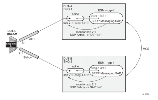
9.4.22. Subscriber Override
This feature provides the ability to override queue and policer parameters (CIR, PIR, CBS, MBS) as well as HQoS parameters (egress aggregate-rate and root-arbiter rate) configured at sla-profile and sub-profile level in order to provide per-subscriber-(host) customizations. The goal is to avoid an explosion of the sub-profiles and sla-profiles to cover all service level combinations. This customization of QoS related parameters can in principle occur during authentication (auth-response message) or during sub-host life time by RADIUS CoA messages.
The QoS parameter customizations are communicated by RADIUS server in form of RADIUS VSAs which can be included in RADIUS-authentication response message or in CoA message.
The Alc-Subscriber-QoS-Override VSA (126) is a string with following layout “direction:type:[key:]values” where:
- Object-type:
- direction represents single character indicating i for ingress and e for egress.
- type represents single character indicating q for queue, p for policer, r for aggregate-rate and a for arbiter.
- key is indicated the queue or policer-id. It is not used in case of aggregate-rate and root-arbiter.
- values indicates actual values preceded with keywords used in CLI (e.g., cir).
Aspects, such as parent, priority level, stats- mode are not accessible through this customization. Instead, a new policy should be created on the node.
The key identifying the subscriber-host in the RADIUS CoA message is accounting-session-id This is different in previous releases, where the service-id and ip-address are mandatory fields in RADIUS CoA message.
The operational value of the QoS objects (queues or schedulers) are derived from different inputs. As in queue/policer parameters, the following hierarchy of inputs are respected (highest priority is the first):
- On-line charging overrides
- RADIUS response/CoA overrides
- Queue overrides configured at sla-profile level
- Queue parameters set in QoS policy level
In the case of scheduler/arbiter-overrides, the following hierarchy of inputs apply:
- ANCP overrides
- RADIUS response overrides
- Scheduler/arbiter parameters as configured in scheduling/policer-control-policy.
The above rules are generic. If any given override mechanism is not yet applicable to policers (or arbiters) it will be skipped. The above rules indicate the priority if all mechanisms are supported.
The QoS overrides received in RADIUS message (in the form of a VSA) are per definition related to a given subscriber-host the given message is referring to. Internally, the overrides are applied on per SLA instance level (queue/policer-overrides) and per-subscriber-level (scheduler/arbiter overrides). The subscriber-overrides are applicable to PPPoE hosts only.
In a dual-homing environment, the adapted values are synchronized through MCS, but they do not need to be persistent.
9.4.23. Dual Stack Lite
Dual Stack Lite feature is supported on the 7710 SR-Series in combination with the MS-ISA to function as a DS-Lite Address Family Transition Router (AFTR).
Dual Stack Lite is an IPv6 transition technique that allows tunneling of IPv4 traffic across an IPv6-only network. Dual-stack IPv6 transition strategies allow service providers to offer IPv4 and IPv6 services and save on OPEX by allowing the use of a single IPv6 access network instead of running concurrent IPv6 and IPv4 access networks. Dual-Stack Lite has two components: the client in the customer network, known as the Basic Bridging BroadBand element (B4) and an Address Family Transition Router (AFTR) deployed in the service provider network.
Dual-Stack Lite leverages a network address and port translation (NAPT) function in the service-provider AFTR element to translate traffic tunneled from the private addresses in the home network into public addresses maintained by the service provider. On the 7750 SR, this is facilitated through the Carrier Grade NAT function.
Figure 132: Dual-Stack Lite
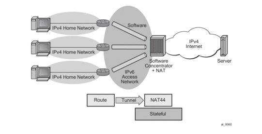
As shown in Figure 132, Dual-Stack Lite has two components, a softwire initiator in the RG and a softwire concentrator, deployed in the service provider network, where control-less IP-in-IP (using protocol 4 - IPv4 in IPv6) is used for tunneling. When using control-less protocol, packets are sent on the wire for the remote softwire endpoint without prior setup of a tunnel.
The softwire initiator in the home network is combined with a routing function, where the default route is passed to the softwire pseudo-interface. Note that there is no NAT function, therefor, the private IP addresses of the home network are encapsulated without source address modification, and forwarded to the softwire concentrator where all NAT is performed. The softwire pseudo-interface unicasts all IPv4 traffic to the IPv6 address of the softwire concentrator, which was pre-configured.
When encapsulated traffic reaches the softwire concentrator, the device treats the source-IP of the tunnel to represent a unique subscriber. The softwire concentrator performs IPv4 network address and port translation on the embedded packet by re-using Large Scale NAT and L2-Aware NAT concepts.
9.4.23.1. IP-in-IP
As shown in Figure 133, IP-in-IP uses IP protocol 4 (IPv4) to encapsulate IPv4 traffic from the home network across an IPv6 access network. The IPv4 traffic tunneling is treated as best-effort with no subscriber management or policy, and does not use ESM. The scale is dependent only on the internal structures of the MS-ISA and CPM, that is, the IP-in-IP model can support more subscribers than an ESM-based approach.
Figure 133: IP-in-IP
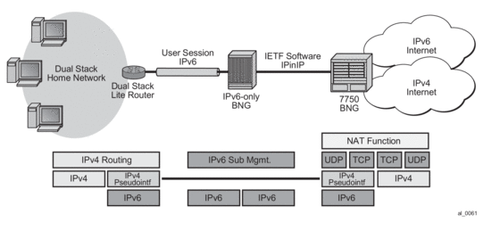
Dual-Stack Lite IP-in-IP is configured through the existing nat command that is inside the CLI statements that are within the base router or VPRN. A service performing large scale NAT supports Dual-Stack Lite.
Dual-Stack Lite expects a routing (non-NATing) gateway in the home, where many different IPv4 inside addresses exist for each subscriber. These inside addresses may overlap other subscriber’s address, especially given the heavy use of RFC 1918 address space.
The lack of control of protocol for the IP-in-IP tunnels simplifies the functional model, since any received IPv4 packet to the ISA dual-stack-lite address can simply be:
- Checked for protocol 4 in the IPv6 header.
- Checked that the embedded IP packet is IPv4.
- Processed as if it were L2-Aware, where the source-IP of the tunnel (the source IPv6 address) is used as the subscriber identifier.
Note that the inside IP address in the NAT, tables must not be the IPv6 address of the tunnel, but the true IPv4 address of any host within the home. The subscriber-id must be the literal IPv6 address (appreciating this may be 34 characters in length).
9.4.23.2. Configuring Dual Stack Lite
Dual Stack Lite is configured on an inside service and uses the existing Large Scale NAT nat-policies and outside pools. Dual-Stack Lite and NAT44 Large Scale NAT can operate concurrently on the same inside and outside services.
Dual Stack Lite is configured using the following CLI:
9.4.23.3. L2TP over IPv6
In this mode, L2TP provides the transport for IPv4 that allows full ESM capabilities on the 7750 SR. From the node’s perspective, the L2TP tunnel is no different in capability to those already supported. Only the underlying transport (IPv6 instead of IPv4) distinguishes this approach.
To support legacy IPv4 access, L2TP over IPv6 is combined with the existing L2-Aware NAT feature as shown in Figure 134.
As ESM is used, scale is limited by the number of ESM hosts supported on a chassis and any associated resources like queues.
Figure 134: L2TP over IPv6

L2TP LNS over IPv6 is supported in both the base routing instance and VPRN that has 6VPE configured.
Like the SR-OS 8.0 LNS implementation, tunnels are terminated on any routing interface, including loopback, SAP, or network port. A single interface simultaneously supports IPv4 and IPv6 L2TP tunnel termination by having two different addresses configured.
For greater scalability, L2TP tunnel and session count per chassis are increased to allow 1 tunnel per session.
NAT capabilities are supported via existing L2-Aware NAT methods. Note that the L2TP LNS over IPv6 may be used without NAT as well and the L2TP sessions may be either IPv6-only or dual-stack.
9.5. L2TP Tunnel RADIUS Accounting
Figure 135: L2TP Tunnel Accounting
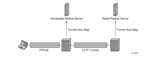
When L2TP tunnel accounting is enabled, except for host or sla-profile-based accounting packets and attributes, the following are additional accounting packets and attributes:
- Accounting packets: tunnel-start/stop/reject; tunnel-link-start/stop/reject — There are no interim updates for L2TP tunnel/session accounting.
- RADIUS accounting attributes:
- Tunnel-Assignment-Id (LAC only)
- Acct-Tunnel-Connection
- Acct-Tunnel-Packets-Lost
These attributes were added into current account-start/stop/interim-update packets (host accounting/sla-profile accounting)
Tunnel level accounting and session level accounting can be enabled or disabled independently.
New accounting packets and related RADIUS attribute list are described in Table 64.
Some considerations of RADIUS attributes are described in RADIUS Attributes Value Considerations
9.5.1. Accounting Packets List
Table 64 describes L2TP tunnel accounting behavior along with some key RADIUS attributes (apply for both LAC and LNS):
Table 64: L2TP Tunnel Accounting Behavior
Act-Packet | When | Key Attributes | Remark |
Tunnel-Start | A new L2TP tunnel is created | Acct-Session-ID | — |
Event-Timestamp | — | ||
Tunnel-Type:0 | — | ||
Tunnel-Medium-Type:0 | — | ||
Tunnel-Assignment-Id:0 | — | ||
Tunnel-Client-Endpoint:0 | — | ||
Tunnel-Client-Auth-Id:0 | — | ||
Tunnel-Server-Endpoint:0 | — | ||
Tunnel-Server-Auth-Id:0 | — | ||
Tunnel-Reject | A new L2TP tunnel creation failed | Acct-Session-Id | — |
Event-Timestamp | — | ||
Tunnel-Type:0 | — | ||
Tunnel-Medium-Type:0 | — | ||
Tunnel-Assignment-Id:0 | — | ||
Tunnel-Client-Endpoint:0 | — | ||
Tunnel-Client-Auth-Id:0 | — | ||
Tunnel-Server-Endpoint:0 | — | ||
Acct-Terminate-Cause | — | ||
Tunnel-Stop | An established L2TP tunnel is removed | Acct-Session-Id | — |
Event-Timestamp | — | ||
Tunnel-Type:0 | — | ||
Tunnel-Medium-Type:0 | — | ||
Tunnel-Assignment-Id:0 | — | ||
Tunnel-Client-Endpoint:0 | — | ||
Tunnel-Client-Auth-Id:0 | — | ||
Tunnel-Server-Endpoint:0 | — | ||
Tunnel-Server-Auth-Id:0 | — | ||
Acct-Session-Time | — | ||
Acct-Input-Gigawords | — | ||
Acct-Input-Octets | — | ||
Acct-Output-Gigawords | — | ||
Acct-Output-Octets | — | ||
Acct-Input-Packets | — | ||
Acct-Output-Packets | — | ||
Acct-Terminate-Cause | — | ||
Tunnel-Link-Start | An L2TP session is created | User-Name | — |
Acct-Session-Id | This is the same as Acct-Session-id in access-request of host auth | ||
Event-Timestamp | — | ||
Service-Type | Framed | ||
Class | — | ||
Tunnel-Type:0 | — | ||
Tunnel-Medium-Type:0 | — | ||
Tunnel-Assignment-Id:0 | — | ||
Tunnel-Client-Endpoint:0 | — | ||
Tunnel-Client-Auth-Id:0 | — | ||
Tunnel-Server-Endpoint:0 | — | ||
Tunnel-Server-Auth-Id:0 | — | ||
Acct-Tunnel-Connection | |||
Tunnel-Link-Reject | A new L2TP session creation is failed | Acct-Session-Id | Should be as same as Acct-Session-id in access-request of host auth |
Event-Timestamp | — | ||
Tunnel-Type:0 | — | ||
Tunnel-Medium-Type:0 | — | ||
Tunnel-Assignment-Id:0 | — | ||
Tunnel-Client-Endpoint:0 | — | ||
Tunnel-Client-Auth-Id:0 | — | ||
Tunnel-Server-Endpoint:0 | — | ||
Acct-Terminate-Cause | — | ||
Acct-Tunnel-Connection | — | ||
Tunnel-Link-Stop
| A established L2TP session is removed | User-Name | — |
Acct-Session-Id | Should be as same as Acct-Session-id in access-request of host auth | ||
Event-Timestamp | — | ||
Service-Type | Framed | ||
Class | — | ||
Tunnel-Type:0 | — | ||
Tunnel-Medium-Type:0 | — | ||
Tunnel-Assignment-Id:0 | — | ||
Tunnel-Client-Endpoint:0 | — | ||
Tunnel-Client-Auth-Id:0 | — | ||
Tunnel-Server-Endpoint:0 | — | ||
Tunnel-Server-Auth-Id:0 | — | ||
Acct-Tunnel-Connection | — | ||
Acct-Session-Time | — | ||
Acct-Input-Gigawords | — | ||
Acct-Input-Octets | — | ||
Acct-Output-Gigawords | — | ||
Acct-Output-Octets | — | ||
Acct-Input-Packets | — | ||
Acct-Output-Packets | — | ||
Acct-Tunnel-Packets-Lost | — | ||
Acct-Terminate-Cause | — |
Notes:
- Errors will occur if there are multiple hosts sharing the same sla-profile instance and then these hosts go to different tunnel.
- 7750 SRs have an internal limitation of 500 pps for accounting messages. This feature shares the same limitation
9.5.2. RADIUS Attributes Value Considerations
- The value of Acct-Tunnel-Connection uniquely identify a L2TP session, and in order to match LAC and LNS accounting record, the value of Acct-Tunnel-Connection is determined by a method shared by LAC and LNS. This means for a given L2TP session, Acct-Tunnel-Connection from the LAC and LNS are the same.
- Current ESM stats are used in Tunnel-Link and tunnel level accounting. This applies for both standard attribute and the 7750’s own VSA.
- Tunnel level accounting stats need to aggregate all sessions stats that belong to the tunnel. Note: there could be sessions come and go before tunnel is down, so system need to remember the stats of every session that has been created within the tunnel.This applies for both standard attribute and 7750’s own VSA.
- The value of Acct-Tunnel-Packets-Lost is the aggregation of all discarded packets on both ingress and egress.
9.5.3. Other Optional RADIUS Attributes
Table 65 lists the optional attributes that could be optionally included in tunnel accounting packet, some of them are applied for link level accounting only.
Table 65: Optional RADIUS Attributes
Attribute | Tunnel/Link |
nas-identifier | Both |
nas-port | Link level only |
nas-port-id | Link level only |
nas-port-type | Link level only |
9.5.4. RADIUS VSA to Enable L2TP Tunnel Accounting
In order to support pure RADIUS-enabled L2TP tunnel accounting on LAC side, the following RADIUS VSA are supported:
Table 66: Supported RADIUS VSAs
VSA | Type | Value |
ALC-Tunnel-Accounting-Policy | String | Policy-name; if the name is disable then this means L2TP tunnel accounting is disabled for this tunnel |
Note: ALC-Tunnel-Accounting-Policy takes precedence over what has been defined in CLI when Alc-Tunnel-Group is also returned.
9.5.5. MLPPP on the LNS Side
With MLPPP, the counter on LNS side is only available for the bundle, not for each link, so the SR OS’s behavior is:
- For each new link session system sends a tunnel-link-start.
- For each link session that is deleted system sends a tunnel-link-stop.
- For all link sessions except the last one system reports 0 for all counters.
- For the last link session, system reports the actual counters for the bundle.
9.6. RADIUS Route Download
The RADIUS route download mechanism periodically polls a RADIUS server for routes to download. The main objective of this feature is to download, in advance, customer-assigned subnets so that they can be re-advertised to the corresponding routing protocols. In this way, subscriber bring up can potentially be done faster (as the routes are already in place and advertised) and, most importantly, reduce the routing protocol churn as subscribers connect and disconnect. The routes being learned through this mechanism could be both managed routes/delegated prefixes as well as the WAN IP assigned to the subscriber in the case PPPoE and un-numbered interfaces are being used.a
The route download process requests the routes to a configured RADIUS server by triggering an access-request message. The key identifier for this message is the username, which is a combination of the system’s name (or an optionally configured value), appended by a dash ( “-”) and then a monotonically increasing integer. The download process sends an access request starting with 1 (such as “hostname-1”) and the RADIUS server replies with an access-accept message and a number of routes embedded within the message. The system then increases the counter and sends another access request (this time being hostname-2) and receive a reply with the next batch of routes to download. The process continues, incrementing the counter by 1 each time until the system gets an access-reject or the maximum number of routes that can be downloaded is reached.
The routes to be accepted are in the following format:
[vrf {vprn-name | vprn-service-id}] prefix-mask {null0 | null 0 | black-hole} [metric] [tag tag-value]
The prefix-mask could be in any form as ‘prefix/length’, ‘prefix mask’ or ‘prefix’ (in the latter case, for IPv4 routes, the mask shall be derived from the IP class of the prefix).
The route formats are supported:
- Framed-Route (RADIUS attribute 22)Framed-Route = "192.168.3.0 255.255.255.0 null0"Framed-Route = "vrf vrfboston 192.168.1.0/24 null 0 0 tag 6"Framed-Route = "vrf 2001 192.168.10.0/24 black-hole 0 tag 8"
- Cisco-AVPair (Cisco VSA 26-1)cisco-avpair = "ip:route = 192.168.3.0 255.255.255.0 null0"cisco-avpair = "ip:route = vrf vrfboston 192.168.1.0/24 null 0 0 tag 6"
IPv6 routes are also supported. The format is based on using the IETF-defined IPv6 Framed-IPv6-Route (attribute 99). The following text shows the supported formats.
- Framed-IPv6-Route (RADIUS attribute 99)Framed-Route = "2001:100:bad:cafe::/64 null0"Framed-Route = "vrf vrfboston 2100:5aaa:dead:beaf::/96 null 0 0 tag 6"Framed-Route = "vrf 3000 2200:1bbbb:dead::/48 black-hole 0 tag 6"
All the routes downloaded will be a new protocol type “periodic”. The downloader process re-starts the AAA requests after a given interval (a configurable value but target refresh rate is 15 minutes) and routes shall be updated according to the following process:
- When the router initiates a new download process, the routes are kept in a temporary table until the download process completes (receives an access-reject from the AAA). The temporary download table is then checked for errors and finally, any changes reflected to the actual routing table.
- Routes no longer present in the download will be removed from the routing table.
- If the AAA server responds with an access-reject for the first username (that is, an implicit empty route-download table), all routes will be removed from the routing table.
- If there are any protocol errors (at the RADIUS level), such as time-out, no response, bad record format, too many records, etc., the download process is suspended and retried after a configurable timer. The minimum retry timer is at least 1 minute and given the light load this represents control-plane-wise (concurrent downloads are not supported) the retries can continue infinitely until the next refresh period occurs, where the download restarts from the beginning. An exponential backoff algorithm with a configured minimum and maximum delay will be used to determine the retry timer.
- In any case, the routes are only purged from the routing table after a complete download process was achieved (properly terminated with an access-reject message). Under any other failure condition, the routes shall remain active. Shutting down the download process should not remove the downloaded routes. A clear command will be provided to clear the periodic routes.
- All the imported routes (blackholes) will be imported into the line-card FIBs to avoid the routing loops caused by announcing the prefixes but not installing the actual blackholes.
9.7. Managed SAP (MSAP)
Managed SAPs allow the use of policies and a SAP template for the creation of a SAP. Although the router supports automatic creation of subscriber hosts in a shared SAP, the most secure mode of operation and common mode is the subscriber per SAP model. In this model, each subscriber is defined with its own VLAN. This feature uses authentication mechanisms supported by the node to provide a SAP.
The reception of a trigger packet initiates a RADIUS or local user database authentication to provide the service context in which the MSAP should be created. The VLAN of the created MSAP is the same as the trigger packet. An MSAP is similar to a regular SAP but its configuration is not user editable and not maintained in the configuration file. The managed SAP remains active as long as the session is active.
The following trigger types are supported:
- DHCP discover (or requests if configured) for DHCP clients. The managed SAP lifetime is defined by the lease time.
- PPPoE PADI for the PPPoE client. The managed SAP lifetime is defined by the session time. The MSAP is installed after the IP address is provided. A short temporary state handles packets between the PADO and ACK.
- ARP defines the managed SAP lifetime. The ARP entry refresh behavior is maintained.
- DHCP6
- PPP
- rtr-solicit (SLAAC hosts)
Multiple trigger types can be enabled on a single capture-sap.
Trigger packets are received on a capture SAP that must be configured in a VPLS service. A capture SAP is defined in a similar way as a regular default SAP but it does not forward traffic. It’s sole purpose is to capture trigger packets for authentication. Refer to the following configuration example:
A capture SAP and default SAP cannot be configured at the same time for a single port with the dot1q encapsulation or for a single port:topq combination with qinq encap. The capture SAP is used if a more specific match for the Q or Q-in-Q tags is not found by the IOM. If a capturing SAP is defined, triggering packets are sent to the CPM. Non-triggering packets captured by the capturing SAP are dropped.
An ingress VLAN ID (VID) type mac filter can be configured on a capture-sap to have additional control on the VLANs that are allowed to initiate a host setup. Other filter types are not supported on a capture-sap.
Capture-sap on a dot1q encapsulated port:
- <port-id>:*Captures any valid single tagged trigger packet on <port-id> for which no more specific SAP or MSAP is found.A single q-tag (<port-id>:tag) is available for authentication.The corresponding Managed SAP is created as: <port-id>:tag
Capture-sap on a qinq encapsulated port:
- <port-id>:*.*Captures any valid double tagged trigger packet on <port-id> for which no more specific SAP or MSAP is found.Both q-tags (<port-id>:tag1.tag2) are available for authentication.The corresponding Managed SAP is created as: <port-id>:tag1.tag2.The optional allow-dot1q-msaps CLI command configured at the capture SAP enables additional support for single tagged trigger packets:
- also valid single tagged trigger packets for which no more specific SAP or MSAP is found are captured on <port-id>
- A single q-tag is available for authentication, the second tag is set to zero (<port-id>:tag.0)
- The corresponding Managed SAP is created as: <port-id>:tag.0
- The config>system>ethernet>new-qinq-untagged-sap command should be configured where a combination of <port-id>:tag1.0 and <port-id>:tag1.tag2 MSAPs co-exist. When not configured, <port-id>:tag1.0 MSAPs attract double tagged <port-id>:tag1.tag2 encapsulated traffic which is either dropped (IPoE traffic) or handled as single tagged traffic causing PPPoE sessions to fail.
- <port-id>:tag1.*Captures any valid double tagged trigger packet with outer tag = tag1 on <port-id> and for which no more specific SAP or MSAP is found.Both q-tags (<port-id>:tag1.tag2) are available for authentication.The corresponding Managed SAP is created as: <port-id>:tag1.tag2.The optional allow-dot1q-msaps CLI command configured at the capture SAP enables additional support for single tagged trigger packets:
- also valid single tagged trigger packets with tag=tag1 and for which no more specific SAP or MSAP is found are captured on <port-id>
- A single q-tag is available for authentication, the second tag is set to zero (<port-id>:tag1.0).
- The corresponding Managed SAP is created as: <port-id>:tag1.0
- It is a prerequisite to have the config>system>ethernet>new-qinq-untagged-sap command configured to enable both <port-id>:tag1.* capture-sap and <port-id>:tag1.0 MSAP to co-exist. The <port-id>:tag1.0 capture-sap cannot be created when not configured.
- <port-id>:*.tag2Captures any valid double tagged trigger packet with inner tag tag2 on <port-id> for which no more specific SAP or MSAP is found.Both q-tags (<port-id>:tag1.tag2) are available for authentication.The corresponding Managed SAP is created as: <port-id>:tag1.tag2.This is an inverse capture-sap that matches on a fixed inner tag with the outer tag identifying the user. The following restrictions apply when an inverse capture-sap is configured on a port:
- Ethernet ports only
- It is not possible to create y.* saps when there is a *.x capture sap present on the port (y=0,1..4094,* and x=1..4094).
- It is not possible to create a y.* network interface when there is a *.x capture SAP present on the port (y=0,1..4094,* and x=1..4094).
- No support for single tagged managed SAP creation
To enable the creation of single and double tagged managed SAPs via a qinq encapsulated capture SAP, following CLI command should be specified:
In addition, new-qinq-untagged-sap should be configured for scenarios as explained previously:
Note that enabling the new-qinq-untagged-sap command affects the behavior of existing <port-id>:tag1.0 SAPs.
Valid single tagged trigger packets will result in the creation of a <port-id>:tag.0 managed sap. With encap-tag-range matching in a local user database, it is possible to specify different MSAP defaults for single or double tagged MSAPs. For example:
A set of mandatory parameters should be provisioned for MSAP creation are as follows:
- Service id: The service context in which the MSAP will be created.
- Interface id: The name of the group-interface context in which the MSAP will be created. The group-interface must exist in the provided service for the MSAP to be installed (routed CO scenario only).
- MSAP policy: The name of the policy that defines the MSAP parameters. The policy must exist in the subscriber-mgmt context.
These parameters can be obtained from the following order of preference:
- Local user database lookup.
- RADIUS attributes.
- Defaults configured at the capture-sap context.
The MSAP parameters can be obtained from a local user database. The local user database should be configured at the capture SAP and group interface context. For example,
# IPoEv4 hosts
# IPoEv6 hosts
# PPP hosts
When RADIUS authentication is still required after local user database authentication, then the authentication policy must be specified in the local user database. In this case no authentication policy may be configured at the group-interface context. For example,
# IPoE hosts
# PPP hosts
The MSAP parameters are configured at the local user database host context. For example,
When RADIUS authentication is required to return the MSAP parameters without prior local user database authentication, then the authentication policy should be configured at the capture-sap context. In a Bridged CO model, the authentication policy specified in the capture-sap will also be used for the MSAP in the VPLS service. In a Routed CO model, the same authentication policy must also be configured at the group-interface context. For example,
The MSAP will not be created if the group-interface name returned from RADIUS has a different authentication policy than the authentication policy configured at the capture-sap.
The following table lists the RADIUS attributes (VSAs) to include in a RADIUS access accept message to obtain MSAP parameters in the RADIUS authentication phase.
Table 67: RADIUS Attributes
Attribute Name | Type | Purpose and Format |
Alc-MSAP-Serv-Id [26-6527-31] | Integer | Service ID of the service context in which the MSAP will be created. |
Alc-MSAP-Policy [26-6527-32] | String | Name of the policy that defines the MSAP parameters. |
Alc-MSAP-Interface [26-6527-33] | String | Name of the group-interface context in which the MSAP will be created. |
MSAP parameters that are not obtained from a local user database lookup, and that are not returned from RADIUS can be specified in the default-msap section of the capture-sap context (last resort):
MSAPs can be created in IES or VPRN group interfaces (Routed CO model) and in a VPLS service (Bridged CO model).
The managed SAP configuration can be persistent. The template MSAP policy is stored with the subscriber host which in turn can be made persistent.
If local user database or RADIUS authentication did not provide all the required information to create the subscriber host (no IP address for example), then the MSAP is created with a short timer while waiting for the host to acquire the missing information. If no host is instantiated when the timer expires, the MSAP is deleted.
Multiple subscribers and/or subscriber hosts can share a single MSAP. The MSAP is created with the first instantiated subscriber host and deleted when the last associated subscriber host is removed from the system. Note that only a single MSAP policy is allowed to be specified for a given MSAP. An attempt to change the MSAP policy by a new subscriber host for an existing MSAP will result in a host setup failure.
MSAPs can be created in a wholesale VPRN service while the corresponding subscriber host or session is terminated in a retail VPRN or IES service. Both wholesale MSAP data (service, group-interface and policy) and retail service id must be provided during authentication.
9.7.1. Sticky MSAP
After a subscriber session ends, the MSAP is removed from the system and the historical data of the subscriber is deleted. Sticky MSAP allows the MSAP to remain even when the subscriber session ends. This feature is only recommended for service providers who do not oversubscribe MSAPs in the network.
Sticky MSAP provides the following benefits.
- Because the sticky MSAP is never deleted, the subscriber can start a session faster; processing time is reduced because the MSAP does not have to be recreated.
- The MSAP may contain valuable historical information for the service provider. Keeping the MSAP provides a means for the service provider to look up subscriber historical data.
The MSAP is only be eligible for stickiness if it was successfully created. The sticky MSAP introduces a new state: idle. An idle MSAP indicates that the subscriber on the MSAP has disconnected and the MSAP is ready for a new subscriber connection. An example is shown below:
The command clear service id id msap removes MSAPs.
| Note: This command can remove MSAPs with active subscribers. To clear only MSAPs without any active subscriber, use the keyword idle-only. |
9.7.2. ESM Identification Process
9.7.2.1. SAP-ID ESM Identifier
Providers migrating from Basic Subscriber Management (BSM) can assign a subscriber to a SAP. The SAP ID ESM identifier makes the transition easier by allowing the operator to continue using the sap-id as a subscriber-ID.
An ESM SAP ID provides the system the ability to:
- Provide access to the SAP ID string in the Python script.
- Allow the automatic assignment of the SAP-ID to a static subscriber or subscriber host.
9.7.2.2. DSLAM-ID
A DSLAM ID provides the system the ability to define a DSLAM-ID string provided through the Python script, RADIUS, or local user database. If the DSLAM-ID was provided, but the subscriber host is instantiated on a regular MDA (a non-HSMDA), the DSLAM-ID will be ignored.
The HSMDA and the ability to aggregate subscribers into DSLAMs for the purpose of QoS, can use the SAP ID to identify subscribers and associated DSLAMs.
9.7.3. Default-Subscriber
This feature provides a default subscriber definition under the SAP. If the object was configured the operator may use ESM without enabling a processing script or a RADIUS authentication policy. In the event both have been disabled any host that was installed for the SAP will be installed with the configured default subscriber ID. If a RADIUS policy was used or if a script was enabled but a subscriber ID was not returned the default subscriber ID will be used.
9.7.4. Multicast Management
The multicast-management CLI node contains the bandwidth-policy and multicast-info-policy definitions. The bandwidth-policy is used to manage the ingress multicast paths into the switch fabric. The multicast-info-policy is used to define how each multicast channel is handled by the system. The policy may be used by the ingress multicast bandwidth manager, the ECMP path manager and the egress multicast CAC manager.
9.7.5. Subscriber Mirroring
This section describes mirroring based on a subscriber match. Enhanced subscriber management provides the mechanism to associate subscriber hosts with queuing and filtering resources in a shared SAP environment. Mirroring used in subscriber aggregation networks for lawful intercept and debugging is required. With this feature, the mirroring capability allows the match criteria to include a subscriber-id.
Subscriber mirroring provides the ability to create a mirror source with subscriber information as match criteria. Specific subscriber packets can be mirrored mirror when using ESM with a shared SAP without prior knowledge of their IP or MAC addresses and without concern that they may change. The subscriber mirroring decision is more specific than a SAP. If a SAP (or port) is placed in a mirror and a subscriber host of which a mirror was configured is mirrored on that SAP packets matching the subscriber host will be mirrored to the subscriber mirror destination.
The mirroring configuration can be limited to specific forwarding classes used by the subscriber. When a forwarding class (FC) map is placed on the mirror only packets that match the specified FCs are mirrored. A subscriber can be referenced in maximum 2 different mirror-destinations: 1 for ingress and 1 for egress.
9.8. Volume and Time Based Accounting
Time and volume-based accounting includes the following components:
- Metering function performing stateful monitoring of the service delivery to the subscriber.
- Communication with an external management system that gets and updates credit per subscriber, notifications of credit exhaustion, and so on.
- Action on credit exhaustion takes pre-defined action when the credit has been exhausted.
9.8.1. Metering
Metering represents the core of time and volume-based accounting. Service usage is typically measured by performing an accounting of the traffic passing through corresponding subscriber-host queues (volume usage) or by keeping lease-state while the given subscriber-host is connected to the network (time usage).
- Statefullness — The accounting information is compared with pre-defined credit expressed in terms of time or volume to monitor service usage.
- Sensitivity — Defining so called activity-threshold allows distinction between subscriber-host being connected and subscriber-host effectively using the service. This is particularly of interest in cases of time based charging.
- Aggregated usage per-category per-subscriber-host — Accounting information can be reported on per-queue per-sla instance of the given subscriber. In many situations, a certain level of aggregation (such as a per-subscriber or HSI ingress and egress traffic) is required to perform meaningful mechanism for pre-paid services.
9.8.1.1. Categories Map and Categories
This feature introduces a new object category-map which defines individual aggregates (such as data in and out, video and data, etc.) and their mapping to individual forwarding queues.
The following output depicts a category-map configured in the subscriber management context.
Based on a category-map the system gathers usage information (volume/time) on a per-sla-instance-per-category basis. In order to do so, statistics of all queues and/or policers forming the category of the given sla-instance are aggregated.
- Single subscriber host (routed CPE) — Single SLA instance.
- Multiple subscriber hosts on the same SAP (bridged CPE) — Single SLA instance. Note that several hosts use the same credit and the renewal of one will cause renewal for all.
- Multiple subscriber hosts on different SAP (bridged CPE) — SLA instance per host.
The per-category usage gathered as described above is compared with per-subscriber-host-per-category credit and when credit is exhausted several actions can be taken.
There are several category-maps pre-configured on the system. The category-map applicable to a given subscriber-host will be derived at the host creation from the RADIUS VSA in an authentication-response, Python script, or static configuration in the local-user-database. All subscriber-hosts belonging to the same subscriber and created on the same SAP (hence, sharing the same sla-instance) must use the same category-map. In case of conflict, (an existing subscriber host has a different category-map than the one derived for the new host) the category-map of the last host will be applied to a given sla-instance. As a consequence, all previous information related to the status of the credit will be lost.
There can be multiple queues and/or policers aggregated into one category. There can be up to sixteen categories in a category map.
9.8.1.2. Quota Consumption
There are two types of quota (credit), volume and time. In volume usage monitoring, the system accumulates byte counters per category-sla-instance and compares it with the assigned quota. Once the credit is exhausted (or threshold for renewal is met) the system attempts to renew it with corresponding management system.
In time-based credit, the distinction between active-usage and active-connection is made by defining an activity-threshold, where an object defines an average data rate under which the subscriber-host is considered silent.
As long as the effective rate of the application usage does not exceed the rate defined by the activity-threshold, the given subscriber host will be considered silent and its corresponding credit will not be used. As long as the application usage exceeds the rate, the application-credit will be consumed (in terms of time).
9.8.1.3. Minimum Credit Control Quota Values
The minimum credit control quota values are one second for time quota and one byte for volume quota. These minimum values are not realistic deployment values for multiple reasons such as effective sampling periods, statistics processing time, RADIUS message load, subscriber scale, etc.
For typical deployment scenarios it is not recommended to implement Credit Control quota values smaller than 60 seconds for time quota and for volume quota the volume that can be consumed in 60 seconds for that category (function of number of queues/policers monitored and their respective rates).
9.8.1.4. RADIUS VSA Alc-Credit-Control-Quota
The quota in the RADIUS VSA Credit-Control-Quota uses this fixed format:
Alc-Credit-Control-Quota = “<volume quota>|<time quota>|<category name>”
- <volume-quota> is specified in bytes (B), in kilobytes (K or KB), in megabytes (M or MB), in gigabytes (G or GB)
- <time-quota> is specified in seconds (s), in minutes (m), in hours (h), in days (d) or a combination (5m30s). A lower unity may never exceed the higher unity: 5m60s is not allowed and should be specified as 6m.
Both volume and time quota should be specified in the attribute but only one credit type (volume or time) is applied per category. The credit-type of a category is configured in the category-map CLI context.
For example, use Alc-Credit-Control-Quota = “0|1h30m|cat1” to grant time quota and Alc-Credit-Control-Quota = “1G|0|cat2” to grant volume quota.
9.8.2. Credit Negotiation Mechanisms
The per-subscriber per-category credit can be obtained by several ways:
- RADIUS during authentication process.
- Static configuration - configured in the config>subscr-mgmt>category-map>category context.
Credit can be expressed by either
- Volume
- Time
The renewal of the credit using RADIUS authentication is triggered by credit exhaustion or (if configured) by depletion of the credit to exhausted-credit-threshold level. If this occurs, the system will send a RADIUS authentication message indicating the corresponding category and usage. The following are several possibilities for the RADIUS server response (as shown in Figure 136):
Figure 136: Threshold Configured/Not Configured
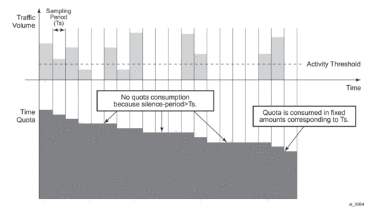
- No authentication response — The system will install out-of-credit action after the original credit has been used.
- Authentication response with reject — The corresponding host is removed after the original credit has been used.
- Authentication response with accept and no credit VSA included — The system will install out-of-credit action.
- Authentication response with accept and credit VSA included — The credit will be installed.The new installed credit is reduced by the amount of credit consumed during credit renewal (i.e. between the start of the credit renewal and reception of an authentication-response). In case the new received credit is less than the credit consumed during credit renewal, then the out-of-credit-action is installed instead.
- Authentication response with accept and credit VSA included — The out-of-credit will be installed. Note that the new credit is always reduced by the amount of credit consumed in time between renewal has been initiated and authentication-respond has been received. In case of a negative result (the newly receive credit is smaller than the amount consumed in the meantime) the test is installed.
In order to identify that the given RADIUS-auth request is related to credit renewal rather than to plain authentication, the node will include empty credit VSAs, depending on categories which has been exhausted. The RADIUS server can identify which category has requested credit renewal.
9.8.3. Action on Credit Exhaustion
System supports configurable actions once the credit for given subscriber is exhausted:
- Sends an SNMP trap and continue (the credit-usage counter is reset).
- Disconnect.
- Changes to a pre-defined service level (such as adjusting the queue rate).
- Blocks the category.
9.8.4. Action on Error-Conditions
During credit negotiation, the number of errors can occur which can lead to a given subscriber-host category with no new credit renewed. This is different from credit exhaustion where a separate configurable action will be taken. The following occurs:
- Sends an SNMP trap and continues.
- Sends a trap and blocks the category.
9.8.5. Applicability of Volume and Time Based Accounting
Volume and time based accounting is applicable to the ESM mode of operation only. Using credit control concept is not mutually exclusive with other accounting methods. In many network implementations the more traditional accounting methods such as XML file or RADIUS accounting will be still used in a combination with the credit concept but with larger intervals. This is helpful when providing overviews of the average usage and service utilization.
9.9. Subscriber Host Idle Timeout
An idle timeout is the maximum time that a subscriber session can be idle before the session is terminated or a connectivity check is started. Idle timeout applies to PPPoE, PPPoEoA, PPPoA and IPoE hosts.
The time/volume based accounting model is used to configure an idle timeout:
- Create a category-map (see Categories Map and Categories)
- Define a category with queues and/or policers to be monitored for activity (packets being forwarded).
- An activity threshold (in kb/s) must be configured for idle timeout to take effect. The activity threshold suppresses background traffic (for example control flows) from activity monitoring.
Example:
In the sla-profile, associate the category-map and optionally define
- An idle-timeout (60 to 15552000 seconds). The default is infinite (no idle-timeout).The idle-timeout can also be specified from RADIUS in an access-accept or CoA message with the [28] Idle-Timeout attribute. A RADIUS specified idle-timeout overrides the CLI- configured value. The values outside the limits are accepted but rounded to these boundaries.
Table 68: Idle-Timeout Attribute
Attribute ID
Attribute name
Type
Limits
Purpose and Format
28
Idle-Timeout
integer
[60..15552000] seconds
0 = infinite (no idle-timeout)
[60..15552000] in seconds
For example:
Idle-Timeout = 3600
- An idle-action:
- shcv-check — Perform a subscriber host connectivity check (IPoE hosts only). Host connectivity verification should be enabled on the corresponding group-interface for the idle-action shcv-check to take effect:
config service ies|vprn service-id subscriber-interface ip-int-name group-interface ip-int-name host-connectivity-verifyIf the shcv check is successful, the subscriber host is not disconnected and the idle-timeout timer is reset to zero. If the shcv check fails, the subscriber host is disconnected (same as terminate).For PPP hosts, the idle-action shcv-check is ignored and has the same effect as “idle-action terminate”- Terminate (default): disconnect the subscriber hosts
- IPoE:Delete the subscriber hostSend a DHCP release message to the DHCP serverSend an Accounting Stop message to the RADIUS accounting server
- PPP:Delete the subscriber hostSend a terminate request message to the CPESend an Accounting Stop message to the RADIUS accounting server
Example
At host instantiation, a timer is initialized to the idle-timeout value (one timer per sla-profile instance). Each queue or policer in the category is monitored for activity over a fixed polling interval:
- During the polling interval:
- if the forwarding rate falls below the configured activity threshold then the timer is deducted by the polling interval (time elapsed).
- If the forwarding rate is above the configured activity threshold then the timer is initialized to the idle-timeout value.
When the timer becomes zero, the idle-timeout-action is performed for all hosts associated with the SLA-profile-instance (all hosts from a subscriber on a single sap and that share the same sla-profile).
9.10. Web Authentication Protocol (WPP)
The Web Authentication Protocol (WPP) is a protocol running between a BNG and a Web portal server. WPP is used for web portal authentication of WLAN users (DHCP Host). It can function like a web portal that can trigger BNG to perform RADIUS authentication for WLAN users, or send user disconnection notification to BNG.
The Figure 137 illustrates high level of call flow of WPP authentication.
Figure 137: WPP Authentication

The following describes WPP authentication call flow:
- When the WLAN user starts a DHCP exchange with a 7750 SR, the router will create a DHCP host from following configurations:
- Sub-id is the default sub-id configured in the sap>sub-sla-mgmt context.
- sla-profile/sub-profile/aa-profile will take the configuration from CLI command grp-if>wpp>initial-sla-profile/initial-sub-profile/initial-app-profile.
- IP address from local or external DHCP server will be assigned to the host.
- When the user sends an HTTP request to visit a web site by browser, the router redirects the HTTP request to the web portal.
- The portal server sends an authentication page to the WLAN user.
- WLAN user enters username and password in the authentication page and submit to the Portal Server.
- The portal server sends a WPP request to router together with the user credentials.
- The 7750 sends an access-request to RADIUS server with user credentials.
- RADIUS returns an access-accept if authentication succeeds.
- The 7750 returns a WPP ack to portal server.
- If it was access-accept, then the router can optionally override the following host properties:
- Sub-id: sub-id from RADIUS. If there is no sub-id from RADIUS, then the host will keep using current sub-id.
- Sla-profile/sub-profile/aa-profile: The system will use the RADIUS server returned values. If the RADIUS server did not return these then the system will try to use the LUDB (in local DHCP server) return values if they are available. If not, the system will try to use the default values configured under SAP.
9.10.1. WPP Configurations
A minimal WPP configurations must include the following:
- WPP portal server — Specifies the name and IP address of the WPP portal server.
- Enable WPP under the group-interface:
- WPP portal server that system should listen to.
- authentication-policy on group-interface that specifies address of RADIUS server.
- def-sub-id under sap>sub-sla-mgmt that is used for DHCP host before user is authenticated by portal server.
- initial-sla-profile and initial-sub-profile that are used for the DHCP host before user is authenticated by portal server. Note: initial-sla-profile should include a ingress filter that has http-redirection entry.
The following is an example configuration:
9.10.2. WPP Triggered Host Creation
In some cases, a 7750 SR can sit behind a Layer 3 device (such as an CMTS), where the router does not participate in client’s DHCP process. Such a use case is different from a normal WPP use case where the routers rely on getting client’s DHCP request to create an initial ESM host.
This feature allows the system to create an ESM host upon successful WPP authentication without creating an initial host.
In the above use case (behind a Layer 3 device) the user also need to configure one or more default hosts on the SAP to allow HTTP redirection without an ESM host. The default-host subnet is the user’s source subnet and the nexthop address is the Layer 3 device’s interface address that connect to the SAP. Users also need to configure the lease-populate l2-header command in the grp-if>dhcp context to make HTTP redirection with default-host work. The grp-if>dhcp context could be shutdown in the meantime.
This feature does not work with wholesale/retail
9.10.2.1. LUDB Support For WPP
The SR OS supports LUDB lookup for WPP authentication. Users can optionally configure LUDB using the grp-if>wpp context to return the WPP-related configuration attributes (such as a portal name, initial-sla-profile, initial-sub-profile, and so on) for an IPoE host. The system can access LUDB when creating the initial host before WPP authentication. The LUDB returned attribute overrides the corresponding configuration under the group-interface context.
A LUDB lookup is performed by the system in the following cases.
- when a host is created
- when the system restores a host after a disconnect
If the WPP LUDB lookup returns an authentication policy, it will be used for WPP RADIUS authentication. When WPP LUDB is configured, the authentication policy on group-interface is optional and only used by the WPP if there is no authentication policy returned from the WPP LUDB lookup.
9.10.3. WPP Multi-Chassis Redundancy Support
The SR OS supports multi-chassis redundancy to WPP. This can be achieved by doing following:
- Create a loopback interface on both 7750 SRs with the same IP address X.
- Use the track-srrp parameter while configuring address X to track the corresponding SRRP instance.
- Configure a portal with the same name and same service-id on both nodes to send WPP packets to the destination address.
- Use an route-policy to export X to the routing protocol. The metric the route X can be set is based on the a specified SRRP state (master or non-master) so that master node can advertise route X with a better metric. Then the WPP packet from the portal will be attracted to the master.
- Only the master process WPP packet, however in case of standby node receives (such as routing is still re-converging) the WPP packet, then standby will shunt the WPP back to master.
- WPP hosts will be synced via MCS.
9.11. One-time HTTP Redirection Overview
With this feature enabled, after an ESM host is created, only the FIRST HTTP request from the host will be redirected to a configured URL with specified parameters. Subsequent HTTP request will go through without being redirected.
This feature could be used by service providers to push a web-page to broadband users for purpose of advertisement, announcements, and such.
A one-time-http-redirection filter could be configured in sla-profile, this filter will be replaced by ingress filter in sla-profile after 1st HTTP request is redirected. There is also a RADIUS VSA (ALC-Onetime-Http-Redirection-Filter-Id) that could be included in access-accept or CoA request to override CLI configuration. The format of ALC-Onetime-Http-Redirection-Filter-Id is Ingr-v4:filter-id; for example, Ingr-v4:1000. If the the filter-id is 0, then system will replace the current one-time-http-redirection filter with ingress filter.
Note: In case of CoA, if the host’s one-time-http-filter has already been replaced then system will just ignore the ALC-Onetime-Http-Redirection-Filter-Id.
If a 7750 SR receives filter insertion via CoA or access-accept when one-time-http-redirection filter is still active then the received filter entries will only be applied to the ingress filter. And after 1st http redirection, the update ingress filter will replace the one-time-http-redirection filter.
This feature only supports IPv4 filter.
9.12. ESM over MPLS Pseudowires
This feature allows IPoE and PPPoE (terminated or L2TP tunneled) subscriber sessions to be backhauled through an Ethernet aggregation network using MPLS pseudowires terminating directly on the BNG. The MPLS pseudowire originates from the first hop aggregation PE (referred to as access PE) upstream of the Access-Node (or directly from a multi-service AN), and terminates on the BNG. Multiple subscriber sessions from a given access-port on the Access-PE can be backhauled over a single P2P MPLS pseudowire towards the BNG. This capability allows the network to scale and does not require a MPLS pseudowire per subscriber between Access-PE and the BNG. The access-port on the Access-PE can be dot1q, q-in-q or NULL encapsulated. The BNG terminates the MPLS pseudowire, decapsulates the received frames, and provides ESM functions including HQoS, without requiring an internal or external loopback. Each MPLS pseudowire is represented on the BNG as a “PW-port” for which SAPs are created. A PW-port can be configured with capture SAP. Both static and managed SAPs are supported. The underlying Ethernet port is required to be in hybrid mode. The feature set is supported for IOM3-XP and HSMDAv2. This feature is supported on the 7750 SR and 7450 ESS in mixed mode.
Figure 138: ESM over MPLS Pseudowire Example
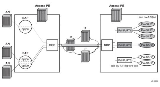
Figure 139: Group Interface Example
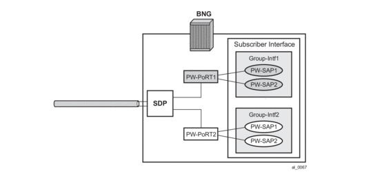
9.12.1. Encapsulation
The subscriber frame encapsulated within the pseudowire is shown in Figure 140. Optional control word is not supported. The SDP could be LDP, RSVP or LDP over RSVP. Hash labels are not supported. SDP is bound to a port or a LAG. In case the SDP is re-routed, the corresponding PW-ports are operationally brought down. The PW-ports are associated with the SDP by configuration.
Figure 140: Subscriber Frame with PWE Encapsulation
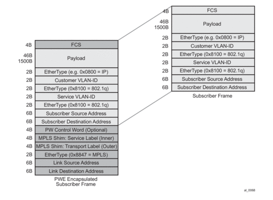
9.12.2. ESM and PW Ports
In BNG deployments, PWs are typically terminated on PW-ports where payload is extracted and processed by ESM on PW-SAPs. There are two modes of operation for PW-ports in SR OS:
- When a PW-port is bound to a specific physical port. A successful mapping between the PW and PW-port requires that the PW terminates on the same physical port (I/O port) to which the PW-port is bound. In this mode of operation, PW-ports do not support re-routing of PWs between the I/O ports. For example, if a PW is rerouted to an alternate physical port due to a network failure, the PW-port will become non-operational.
- When a PW-port is independent of the physical port (I/O ports) on which the PW is terminated. The PXC based PW-port is anchored/bound on the termination side of a port cross connect PXC (which can be either a pxc sub-port or a pxc lag) under an internally created fwd-path-ext (FPE) PW. The benefit ofpeer 10.20.1.2 create such PW-Port is that it continues to provide services in cases where PW is switched between the I/O ports due to a network failure.
9.12.2.1. ESM on PW-Port Bound to a Physical Port
9.12.2.1.1. QoS Support
QoS is supported for ESM over PW SAPs as with ESM over regular SAPs, and includes currently supported models.
- FC to queue mapping
- H-QOS
- Per-subscriber HQOS (service scheduler child to port-scheduler parent).
- PW SAP queues attached to H-QOS scheduler by a parent statement.
- Scheduler attached to port scheduler by a port-parent statement.
- Direct service queue to port-scheduler.
- Aggregate-rate-limit.
9.12.2.1.1.1. Bandwidth Control at PW Port Level via Vport
Bandwidth control per PW-port (per AN or per AN/ per service), via vport.
- The vport can be created on the binding port.
- The vport can be associated with the PW port either via static assignment or dynamic selection via inter-dest-id (returned from RADIUS or DHCP for a host).
- Aggregate-rate-limit can be configured to shape the egress traffic across all hosts associated with the vport via inter-dest-sting match or via static association of underlying PW port with the vport.
The following output displays a dynamic vport selection based on an inter-dest-id configuration.
The following output displays a static assignment of PW port to vport configuration.
9.12.2.1.1.1.1. Last Mile Shaping
With normal Ethernet aggregation in the next-mile, when last-mile shaping is on, fixed encapsulation-offset is calculate based on the last-mile encapsulation type and the next-mile encapsulation (26 Bytes with q-in-q). This offset is applied to the frame, and the ATM overhead is then dynamically calculated on the adjusted size. The resulting dynamically calculated overhead in the data-path is then applied to the queue-rates and the subscriber aggregate-rate.
With this feature of backhauling subscriber sessions using MPLS PW in the aggregation network. The last mile does not see any MPLS PW overhead. The next-mile includes overhead due to the PW encapsulation shown in Figure 140. Therefore, when last mile shaping is enabled, the fixed encapsulation-offset is calculated based on the difference between last-mile encapsulation type and next-mile encapsulation, The next-mile encapsulation takes into account the additional PW overhead, which includes:
14B Ethernet header + [4B] (optional network interface Q-tag) + MPLS Labels (variable)
In the data-path the actual PW encapsulation overhead, taking into account the MPLS labels which could be variable (with FRR or PHP) is tracked, and is applied to the computed “encapsulation offset”. This adjusted “encapsulation offset” is applied to the frame. The ATM overhead is then dynamically calculated on the adjusted size, and applied for last mile shaping (to queue-rates and subscriber-aggregate-rate). Note that there is no change from ESM over normal SAPs, in how last-mile shaping is triggered or how the last mile encapsulation type is determined (via configuration in egress context of subscriber profile or dynamically learned from Access-Loop-Encapsulation sub-TLV in vendor specific PPPoE tags).
9.12.2.1.2. BNG Redundancy with ESM over Pseudowire
This feature provides support for stateful BNG redundancy (when the far-end aggregation PE (A-PE) is dual-homed to two BNGs terminating subscriber sessions over MPLS pseudowires (PWs) that are initiated from the A-PE and provides ESM). Subscriber state between BNGs is synced using MCS.
9.12.2.1.2.1. Epipe-Based Aggregation Service
For an Epipe based aggregation service, the redundancy is based on active/standby PWs from A-PE to dual BNGs. A-PE signals active/standby pseudowire status to peer BNGs. An SRRP instance per PW port (group-interface) is required on the BNG with messaging SAP on each PW port. BNG terminating active PW assumes the mastership for the SRRP instance on the corresponding PW port. SRRP state is tied to the state of the messaging SAP. The messaging SAP goes down when the underlying PW-port goes down, based on PW status bit signaled by the A-PE.
In this model, there is no SRRP message exchange between the two BNGs, as there is no Layer 2 path between the BNGs. The purpose of SRRP is to get SRRP-aware routing for subscriber routes and managed routes, and/or to be able to use the redundant (shunt) interface. Downstream traffic for a subscriber that ingresses the backup BNG can only be shunted to the active BNG, if the corresponding subscriber-interface on the backup BNG is operationally UP. This can be achieved by creating a second empty group-interface (without SAPs) on the same subscriber-interface with the knob 'oper-up-while-empty' configured. Multiple PWs with endpoint configuration is not supported on the BNG.
Figure 141: BNG Redundancy Based on Active/Standby PW Signaling
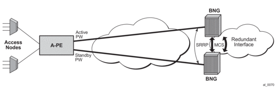
Sample Configuration on Master BNG
Sample Configuration on Slave BNG
9.12.2.1.2.2. Sample Configuration on A-PE
9.12.2.1.2.2.1. VPLS-Based Aggregation Service
With VPLS based aggregation service from A-PE, normal SRRP message exchange can take place between the primary and backup BNGs. Master-ship decision and switch-over is based on SRRP. SRRP instance is configured per group-interface corresponding to PW port. Fate-sharing groups (FSG) can be configured for a set of SRRP instances (for example, SRRP instances corresponding to PW ports sharing the same subnet). Standard oper-group grp-id would need to be configured with messaging SAPs for all PW ports that are in the same FSG, and monitor-oper-group grp-id would need to be configured under each SRRP instance in same FSG. Existing SRRP support defined in Triple-play services guide for ESM over regular group-interfaces and subscriber SAPs is applicable identically to ESM over PW ports and PW SAPs.
Note: With PW over ESM, redundancy in the aggregation network based on MC-LAG between A-PE and dual BNGs is not supported.
Figure 142: BNG Redundancy with VPLS Based Aggregation Service
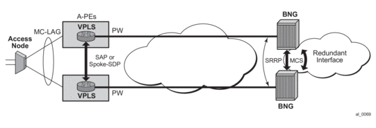
9.12.2.1.2.2.2. Sample BNG Redundancy Configuration with VPLS Service on A-PE
9.12.2.1.2.2.3. Sample BNG Redundancy Configuration with VPLS Service on A-PE
9.12.2.1.2.2.4. A-PE Configuration with VPLS Aggregation Service (A-PE2)
9.12.2.1.2.3. Show Commands Related to Active/Standby Pseudowire on Dual BNGs
The following example shows SRRP status, subscriber host, and routing information on master BNG:
The following shows SRRP status, subscriber host, and routing info in slave BNG:
9.12.2.2. ESM on PXC-Based PW-Ports
This section provides an example on how to configure PW-Port based capture SAP that is used in ESM. For more information on PXC Based PW-Ports, refer to the SR OS Services Overview Guide.
PXC Configuration
The following is a PXC configuration example:
With this configuration, ports 1/1/1 and 2/1/1 are auto-provisioned in hybrid mode operating as individual loopback ports. The SR OS system will automatically create a pair of sub-ports per PXC. Those sub-ports are by default in shutdown state:
For redundancy purposes and/or increased bandwidth, the PXC sub-ports are aggregated in a LAG:
FPE Configuration
A PW-port is associated with PXC via an FPE configuration. FPE configuration facilitates creation of an internal tunnel over PXC. This tunnel is used to map the external PW to the PW-port. For more information on FPE, refer to SR OS Interface Configuration Guide.
The following is an FPE configuration example:
The association between xc-a/b (cross-connects) and LAG IDs is performed arbitrarily by the operator. For example, it is allowed to associate xc-a with lag-id 2 (which includes PXC sub-ports on the .b side) and xc-b with lag-id 1 (which includes PXC sub-ports on the .a side). However, the FPE will always assign the .a side of the pxc sub-ports to the transit side of the cross-connect, while the .b side of the pxc subport will be assigned to the termination side of the cross-connect. Refer to the PXC Based PW-Ports section in the Layer 2 Services and EVPN Guide: VLL, VPLS, PBB, and EVPN, for further information about transit/termination side of the cross-connect.
PW-Port Creation
The PW-port must be explicitly created in the SR OS, before mapping between PW and PW-port can be performed.
SDP Creation for the External PW
The following displays an SDP configuration for the external PW.
The PW can be static or dynamically signaled, with MPLS or GRE transport.
Mapping Between the External PW and the PW-Port
The stitching of the external PW and PW-port is configured through an Epipe in vc-switching mode.
Capture PW-SAP Creation
PW-SAPs can be configured as capture SAPs. In this example, a capture PW-SAP with s-tag 3 is created on the pw-port 100.
From here, ESM functionality is applied to the PW-SAP in the same manner as on any other regular SAP.
Cross-Connecting SAPs to PW-Ports
In addition to PW termination, a PW-port can become a terminating point for a regular SAP. For example:
In this example, the outer VLAN tag 10 in the payload is removed on ingress and the payload is delivered to the PW-Port where it can be mapped to a capture PW-SAP. This scenario allows traffic distribution from a single I/O port to different EMS termination points (anchor line cards) based on outer VLANs.
9.13. Logical Link Identifier (LLID)
This feature enables service providers to track subscribers on the basis of a virtual-port known as logical line ID (LLID). The LLID (an alphanumeric string) is a logical identification of a subscriber line. Mapping of physical line of a subscriber to LLID is performed via pre-authentication with a separate AAA server than the AAA server used for authenticating the subscriber session during normal access authentication.
LLID serves the purpose of abstracting the physical line of the user from the ISP. If the user moves to a new physical line, the RADIUS server database maintaining the physical line of the subscriber to LLID is updated. Because a subscriber’s LLID remains same regardless of subscriber’s physical location, using LLID gives service provider a stable and secure identifier for tracking subscriber.
The local user database assigned to the PPPoE node under the group interface can have both a pre-authentication policy and an authentication policy. The purpose of the pre-authentication policy is to retrieve the LLID from the AAA server. The pre-authentication will only extract the calling-station-id attribute (0x31) which is used as the LLID, anything else returned during pre-authentication are simply ignored. If the pre-authentication is missing the LLID, the session will move on to the authentication policy. In the authentication policy that follows, it is possible to use the LLID as the calling-station ID.
It is possible to convey LLID from the LAC to the LNS. The LLID is retrieved through PPPoE pre-authentication where the returned RADIUS attribute calling station ID is used as the LLID. This LLID is selectable attribute in L2TP as a calling-number (AVP 22) to be passed from LAC to LNS. At the LNS, the subscriber calling station number is retrieved from AVP 22 and can be included as an attribute during authentication.
9.14. Open Authentication Model for DHCP and PPPoE Hosts
9.14.1. Terminology
LUDB – Local User Database configured within the 7450 ESS and 7750 SR
- IP Address Assignment via DHCP Relay — IP address assignment request (DHCP or IPCP) from the host is relayed to an internal or external DHCP server. Gi-address must be present in this relayed request while the pool name is optional. The internal DHCP server may select the IP address from is local pool based on the gi-address or based on the pool-name present in the request. The IP address selection method is configuration dependent. Third party DHCP servers may consider additional fields in IP address selection process (mac address, circuit-id, and so on).
- IP Address Assignment via DHCP Proxy — A preconfigured IP address in LUDB or RADIUS server is handed out to the host via a DHCP proxy function. This proxy function responds natively using DHCP protocol to the IPoE host. Although PPPoE hosts are not utilizing DHCP protocol, the DHCP proxy functionality within the server is still needed for successful IP address delegation to PPPoE hosts.
9.14.2. LUDB and RADIUS Access Models
During the subscriber-host instantiation phase, various parameters for the hosts are gathered from a single or multiple sources. These parameters represent the level of service within the router to which the host is entitled. Some of the parameters are mandatory for subscriber instantiation while others are optional. The following lists the parameter sources in the order of priority:
- LUDB
- RADIUS
- DHCP Server — The DHCP server directly queries LUDB
- DHCP option processed on DHCP ACK that is indicated in subscriber identification policy.
- Extraction from the DHCP Ack via Python (IPv4 only)
- Defaults that are statically configured on the node (SAP, msap-policy, capture-sap, and subscriber-identification-policy).
In most cases, the host IP address assignment process is controlled by the parameters returned via LUDB or RADIUS. As such, the IP address delegation is integral part of the host instantiation process and will consequently be described in the following sections.
9.14.3. No Authentication
IPoE and PPPoE v4/v6 hosts on static SAPs can be instantiated without the need to access LUDB or RADIUS server. In this case, the default subscriber host parameters (sla-profile, sub-profile, subscriber-id) must be provisioned statically under the SAP. The IP address assignment is provided by internal or external DHCP server. The IP address selection on the router based DHCP server is based on the gi-address while third party DHCP servers may provide additional means to select the IP address (mac-address, circuit-id, and so on).
A DHCP pool name cannot be provided by an SR-series router DHCP relay agent, since the LUDB and/or RADIUS are not utilized.
This model does not support IP address delegation via DHCP Proxy function since there is no LUDB or RADIUS server available that can supply pre-configured IP address.
Host instantiation without LUDB or RADIUS access on dynamic VLANs (capture SAP and consequently mSAP) is not supported.
9.14.4. LUDB Only Access
Subscriber-host authentication, identification and IP address assignment can be performed via LUDB without the need to access the RADIUS server.
The LUDB is normally configured under the group-interface>ppp/dhcp hierarchy and can provide subscriber-identification parameters as well as IP addressing parameters:
Pool names for DHCP relay function (IPv4, IPv6 IA-NA, IPv6 IA-PD)
Fixed IP addresses – IPv4, IPv6 IA-NA, IPv6 IA-PD and IPv6 SLAAC prefix.
In case of capture SAP, the LUDB name configured under the capture SAP must much the LUDB name under the group-interface>dhcp/ppp hierarchy. If the LUDB names do not match, the subscriber-host instantiation will fail.
9.14.5. LUDB Access via DHCPv4 Server
In case that the IPv4 addressing assignment is facilitated by the DHCPv4 relay and an internal DHCPv4 server, the DHCPv4 server itself can query the LUDB for IPv4 address information. LUDB can provide a v4 pool name and IPv4 DHCP options to the DHCPv4 server or it can instruct it to use the gi-address as the IPv4 address selection mechanism.
ESM strings can also be provided via LUDB queried by the DHCPv4 server.
If LUDB access via DHCPv4 server is provided in addition to other authentication means (another LUDB under the group-interface, or RADIUS server), the ESM strings from the LUDB under the grp-interface or from the RADIUS server will have priority over the ESM strings configured under the LUDB accessed by the DHCPv4 server. On the other hand, the IPv4 addressing information will have the highest priority from the LUDB accessed directly by the DHCPv4 server.
Accessing LUDB directly via DHCPv4 server should be used in rare and exceptional cases.
LUDB access under the group-interface, possibly complemented by the RADIUS server will provide necessary means for subscriber-host instantiation in majority of use cases.
9.14.6. RADIUS Only Access
Similar to LUDB-only access, RADIUS server can provide all the necessary information for subscriber-host instantiation, including the IP addressing parameters (pool names or IP addresses/prefixes). Authentication-policy which defines the RADIUS access must be applied to the group-interface.
In case of capture SAP, the authentication policy must be applied under the capture SAP. This authentication policy name must match the authentication policy name that is configured under the group-interface. Otherwise, the host instantiation will fail.
9.14.7. Consecutive Access to LUDB and RADIUS
LUDB and RADIUS access can be combined during subscriber-host instantiation phase.
Configuration wise, LUDB must be referenced under the group-interface>dhcp/ppp/pppoe hierarchy (and possibly under the capture SAP), while the authentication-policy is specified within the LUDB. In this fashion, LUDB access is followed by RADIUS access. The subscriber-host parameters retrieved from both sources are combined with LUDB parameters being prioritized over RADIUS parameters in case that both sources return the same parameters.
In case that LUDB and authentication policy are configured simultaneously under the group-interface (and possibly under the capture SAP), the RADIUS authentication policy will be evaluated and LUDB will be ignored.
9.14.8. RADIUS Fallback
In case that RADIUS server is not accessible (non-responsive), the host instantiation phase can be:
Terminated in the case the there is no fallback action within authentication policy specified.
Continued within LUDB if the fallback action within the authentication-policy references LUDB.
Continued without any response from RADIUS. Subscriber-host will be instantiated if defaults parameters are statically configured or the instantiation will fail in case that the defaults are not available.
The fallback action takes effect once the preconfigured RADIUS timeout period expires.
RADIUS fallback is currently not supported for DHCPv6 hosts.
9.15. Flexible Subscriber-Interface Addressing (Unnumbered Subscriber-Interfaces)
9.15.1. Terminology
Subscriber host — A representation of an external host requesting a service. Each such host is fully instantiated within the 7450 ESS and 7750 SR for the purpose of providing traffic control and billing services (for example, QoS, filtering, antispoofing, accounting). The external hosts may represent variety of devices such as regular PCs, STBs, residential gateways, CPEs, VoIP devices. In most cases, the external host will run a DHCPv4/v6 or PPPoEv4/v6 client. DHCP and PPPoE initiation messages from such clients will trigger host instantiation within the router. For this the subscriber host term can be interchangeably used with a term DHCP client or PPPoE client.
9.15.2. Flexible Subscriber-Interface Addressing for IPOE/PPPOE v4/v6 Subscribers
In certain wholesale/retail environments, the wholesale provider that own the 7450 ESS and 7750 SR -BNG does not know the IP addresses that the retailers will assign to their clients in advance. For this reason, wholesaler’s BNG must accept any IP address from retailers and consequently pass it to the client during subscriber-host initiation phase.
Figure 143: Use Case for Flexible IP Addressing Model
Flexible addressing of the subscriber-interface assumes two deployment scenarios:
- Subscriber-interface is unnumbered — For example, there is no explicit assigned IP address. Instead the subscriber-interface borrows the IP address from an existing interface that is operationally UP and is located in the same routing instance (router | vprn).Note that an interface must have an IP address assigned in order to be operationally UP. Therefore, an unnumbered subscriber-interface must reference another existing interface that is operationally UP in the same routing instance. The subscriber-interface will borrow the IP address from the referenced interface.In this case any IP address can be assigned to the subscriber host under the unnumbered subscriber-interface. The subscriber IPv4 address will be installed in the FIB as /32 route while IPv6 address will be installed as an entry of the length anywhere between 64 and 128 bits.
- Subscriber-interface is numbered — The IP address/prefix is explicitly configured and solely owned by the subscriber-interface.In this case, all subscriber IP addresses/prefixes that fall under the subnet/prefix dictated by the configured subscriber-interface IP address/prefix will be directly aggregated under the subscriber-interface subnet. As such they will occupy a single entry in the FIB. The rest of the subscriber hosts with IP addresses/prefixes that fall outside of the configured range will be installed in the FIB as individual entries (/32 for IPv4 and an entry of the length anywhere between 64 and 128 bits for IPv6 hosts).
9.15.3. Default Gateway in IPv4 Flexible Addressing
In scenarios where subscriber host IPv4 address lies within the configured subscriber-interface subnet, the default-gw IPv4 address for the host will be one of the subscriber-interface IPv4 addresses. In this case, the service provider is aware of the IPv4 addressing scheme in the BNG and as such it will supply the DHCP client with the appropriate default-gw IPv4 address via LUDB, RADIUS or DHCP Server (in that order of priority).
In scenarios where the retail service provider wants to maintain independence from the IPv4 addressing scheme deployed in the BNG (that is controlled by wholesaler), the retailer can always supply its own IPv4 address, the subnet mask and the default-gw IPv4 address. But if the default-gw IPv4 address and/or subnet mask is not supplied by the retailer, then they will be auto-generated by the BNG. Once the default-gw IPv4 address is auto-generated, it will be sent to the requesting DHCP client via DHCP offer in option 3 (RFC 2132, Router Option, section 3.5). There is no additional configuration needed for this action. The BNG will automatically detect whether the default-gw IPv4 address is supplied via LUDB, RADIUS or DHCP server and it will act correspondingly.
The default-gw IPv4 address is auto-generated based on the assigned IPv4 address/mask by setting the last bit of the assigned host IPv4 address to binary 01 or binary 10. For example if the subscriber host’s assigned IPv4 address is 10.10.10.10 255.255.255.0, then the default-gw IPv4 address is set to 10.10.10.1. If the assigned IPv4 address is 10.10.10.1 255.255.255.0, then the auto-generated default gateway IPv4 is set to 10.10.10.2.
The default gateway IPv4 address will always have to be within the subscriber’s subnet. If it is not, the behavior might be inconsistent. For example:
- RADIUS (or DHCP) returns IP@, mask and def-gw:
- IP 10.10.10.1
- Subnet mask 255.255.255.0
- Def-gw 10.10.0.254
The subscriber will be successfully instantiated in the BNG but the client may not ARP for a default-gw outside of its configured subnet. Whether the client will or will not ARP for a default-gw outside of its configured subnet will depend on the implementation in the RG and CPE.
- RADIUS returns IP@ and subnet mask.
- In this case the auto-generated default-gw IPv4 address will always be within subscriber’s subnet.
Flexible IPv4 addressing with auto-generated default-gw is supported only in Routed Central Office (RCO) model with routed residential gateways (RGs) or CPEs. In RCO model with bridged residential gateways or CPEs, the default-gw IPv4 addresses and the assigned IPv4 addresses may overlap. Once the IPv4 address of the default-gw is auto-generated, it is possible that the second host behind the bridged residential gateway or CPE is assigned the same IPv4 address as the IPv4 address of the default gateway of the first host. Such hosts would not be able to communicate with outside world.
For example:
RADIUS or DHCP server assigns IPv4 address and subnet mask to the first host in a bridged environment:
IP1: 10.10.10.1
Auto-generated default-gw IPv4 address: 10.10.10.2
Since the RADIUS and DHCP Server are not aware of the auto-generated default-gw, they may assign the following IPv4 address to the second host that comes on-line:
IP 2: 10.10.10.2 (same IPv4 address as the default-gw IPv4 address of the first host)
Auto-generated default-gw IPv4 address: 10.10.10.1
Now the first host will forward all traffic outside of the configured subnet to the second hosts which will discard this traffic, effectively rendering this operation model non-deployable. And vice versa.
9.15.4. IPv4 Subnet Sharing
Subnet sharing between the hosts in flexible IPv4 addressing model is supported. In other words, in flexible IPv4 addressing model the operator can assign all IPv4 addresses (minus one – the default-we IPv4 address) from a given subnet. In this fashion, all subscribers (routed RGs or CPEs) within a single subnet can share the same default gateway.
For example if the operator owns the IPv4 subnet 10.10.10.0/24, then one IPv4 address can be set aside for the default-gw (for example 10.10.10.254) and the remaining addresses can be assigned to the subscriber (routed RGs or CPEs). An example would be:
RG1: IP=10.10.10.1/24 def-gw 10.10.10.254
RG2: IP=10.10.10.2/24 def-gw 10.10.10.254
RG3: IP=10.10.10.3/24 def-gw 10.10.10.254
:
RG100: IP=10.10.10.100/24 def-gw 10.10.10.254
The subnet sharing is also supported in conjunction with auto-generated default-gw IPv4 address. The implication of this is that the IPv4 address of the default-gw can collide with the same IPv4 address already assigned to an existing subscriber. This is not an issue for routed RGs or CPEs since the BNG will always answers ARPs for the IPv4 address of the default-gw with its own MAC address. However, local-proxy ARP functionality in the 7450 ESS and 7750 SR -BNG must be enabled to support this.
This behavior can be further clarified with the following example.
Let’s assume that we have scenario with two routed RGs:
RG-1, IP=10.10.10.0/24, default-gw IP=10.10.10.1
RG-2, IP=10.10.10.1/24, default-gw IP=10.10.10.0
Once RG-1 ARPs for its default gateway of 10.10.10.1, the BNG will reply with its own MAC address.
Now that host RG-1 has resolved ARP for it default-gw (MAC address pointing to the router), it can send traffic to the outside world via the BNG. When such traffic arrives to the router, the destination IPv4 address of the received packet will determine the forwarding decision within the router. If the destination IPv4 address matches the IPv4 address of any subscriber (RG) instantiated within the system, the traffic will be forwarded to the that RG. This also includes the case where the destination IPv4 address is the default-gw IPv4 address (10.10.10.1), which represents just another RG within the router. The traffic will be consequently passed from RG-1 via 7450 ESS and 7750 SR to RG-2.
9.15.5. IPv4 Subnet Mask Auto-Generation
The subnet mask corresponding to the IPv4 address assigned to the subscriber is auto-generated in case that the IPv4 addressing authority (LUDB, RADIUS or DHCP Server) does not supply it. The subnet mask is derived from the IPv4 address of the subscriber and possibly the default-gw IPv4 address and it is the smallest subnet that contains both, the IPv4 address of the subscriber and the default-gw.
For example if the RADIUS received IPv4 address is 10.10.10.138 and the received default –gw IPv4 address is 10.10.10.170 , then the subnet mask will be auto-generated and set to 255.255.255.192 ( /26).
138 = 10001010
170 = 10101010
192 = 11000000
In case that neither the subnet mask nor the default-gw are returned, then both would be auto-generated:
- Subnet mask would be set to /31
- Default-gateway which must belong to the subscriber’s subnet would be set to 10.10.10.139.
In cases where the host IPv4 address and the default-gw are directly supplied by the addressing authority but the subnet mask is missing, the subnet mask auto-generation may cause the host part of the default-gw IPv4 address to become a broadcast IPv4 address. If this is an issue, then it can be avoided by directly providing the subnet mask via the addressing authority.
9.15.6. Local-proxy-arp and arp-populate
Local-proxy-arp and arp-populate are two commands that are relevant only to IPoEv4 hosts.
Local-proxy-arp command ensures that the router answers ARP Requests with its own MAC address for any ‘active’ IPv4 address under the subnet on which the ARP request arrived. The ‘active’ IPv4 address is considered the one that is assigned to an already instantiated hosts or the default-gw (even auto-generated).
In absence of local-proxy-arp command, the only ARP Request that the routerwill answer is the one for the statically configured IPv4 addresses of the subscriber-interface. In flexible IPv4 addressing, the IPv4 address of the default-gw does not necessarily match any of the configured subscriber-interface IPv4 addresses. The ARP Request for such default-gw IPv4 address would go unanswered. Consequently, the subscriber hosts would not be able to communicate with outside world. Therefore, the flexible IPv4 addressing requires that the local-proxy-arp command is configured.
Arp-populate command disables dynamic learning of ARP entries (IPv4<->MAC mapping) on an interface based on the ARP protocol. In this case, the ARP table is populated based on the DHCPv4 lease state table which contains IPv4<->MAC mappings obtained via DHCP processing during the host instantiation phase. Arp-populate functionality is highly desirable in case of flexible IPv4 addressing.
When the arp-populate command is disabled the ARP entries are dynamically learned based on the ARP protocol. This, in conjunction with flexible IPv4 addressing may cause certain issues. Consider the following example:
- The subscriber-host is instantiated in the 7450 ESS and 7750 SR
- The subscriber-interface is unnumbered
- The ARP table does not contain an ARP entry for the subscriber-host
In this case, downstream traffic towards the subscriber host will trigger the router to send ARP Request for the subscriber host IPv4 address. The router needs to know the MAC address of the subscriber-host in order to forward traffic. Since the subscriber-interface is unnumbered, the source IPv4 address of the ARP request is unknown and consequently the ARP request will not be sent. As a result, downstream traffic is dropped.
Note however that the above example is an unlikely scenario. If the subscriber host sends the ARP request for the default-gw first, the router would create an entry in the ARP table for it and the issue would be resolved. This is the most likely outcome since the subscriber host will always try to initiate communication with the outside and therefor ARP for the IPv4 address of the default-gw (which is a 7450 ESS and 7750 SR ).
9.15.7. Gi-address Configuration Consideration
With flexible IPv4 address assignment, the gi-address can be configured as any IPv4 address that is already assigned to an interface (loopback interface, regular interface attached to physical port or subscriber interface) within the same routing instance (VRF or GRT).
9.15.8. PPPoE Considerations
PPPoE subscriber hosts do not have the concept of default-gw. Consequently the default-gw auto-generation concept does not apply to PPPoE hosts.
9.15.9. IPoEv6 Considerations
The default-gw for IPoEv6 hosts is link-local IPv6 address. Since this address is always present, there is no need for auto-generation during the subscriber instantiation time.
SLAAC hosts are installed as /64 entries, the length of the installed DHCP-PD prefix is dictated by the prefix-length and the DHCP-NA hosts are installed as /128 entries.
9.15.10. General Configuration Guidelines for Flexible IP Address Assignment
Flexible IP addressing for IPoE/PPPoE v4 and v6 hosts is by default disabled. In other words, the subscriber hosts will be instantiated in the BNG with ability to forward traffic only if their assigned IP addresses belong to one of the configured subnets/prefixes that are associated with the subscriber-interfaces. IPv4 and IPv6 cases will be examined separately:
IPv4:
By default, IPoE and PPPo subscriber host creation will fail in the following two cases:
- The subscriber-interface does not have an IPv4 address configured, and therefore it will be operationally down. This configuration is also known as unnumbered subscriber-interface.
- The subscriber-interface does have an IPv4 address configured but the IPv4 address assigned to the subscriber host itself is outside of the subscriber-interface configured subnet(s). In such case the host will be instantiated but the forwarding will be disabled.
Subscriber host instantiation and forwarding can be explicitly enabled for both cases above with flexible IP addressing functionality.
For case 1, this can be achieved by borrowing an IP address for the subscriber-interface from any interface that is operationally up within the given routing context. This functionality can be enabled with the following command:
To enable forwarding for the subscribers whose IP address falls outside of the configured subnet under the subscriber-interface (case 2), the following command must be entered:
The above commands (unnumbered and allow-unmatching-subnets) are mutually exclusive. In addition, the unnumbered command can be configured only if the subscriber-interface does not have an IP address already configured. Otherwise the execution of this command will fail.
In both of these cases the host will be installed in the routing table as /32.
IPv6:
For IPv6 there is a single command that will enable flexible IP addressing for both cases:
- IPv6 prefixes are not configured under the subscriber-interface>ipv6 node
- IPv6 prefixes are configured but the actual address or prefix assigned to the subscriber (via DHCP, LUDB or RADIUS) is outside any prefix that is configured under the subscriber-interface>ipv6 hierarchy.
This single command is:
To summarize, the following scenarios are possible:
- PPPoEv4
- An IPv4 address under the subscriber-interface is configured
- By default hosts outside of the sub-intf subnet are instantiated but they are in a non-forwarding-state. Traffic is dropped.
- allow-unmatching-subnets is configured. This command is allowed only if subscriber-interface has also configured its own IPv4 address(es). In this case the IP address for IPCP negotiation is one of the sub-intf addresses. Hosts outside of the sub-intf subnets are instantiated and forwarded.
- The unnumbered <ip-address | intf> command is not allowed in this scenario.
- An IPv4 address under the subscriber-interface is not configured
- By default, the subscriber-interface is operationally down. Subscribers cannot be instantiated.
- The allow-unmatching-subnets command has no effect since subscriber-interface does not have an IPv4 address configured and is therefore operationally down. No subscribers can be instantiated.
- The unnumbered <ip-address | intf> command is the only viable option in this case. The subscriber-interface borrows an IPv4 address from another interface that is operationally UP and consequently this allows subscribers to be instantiated. This command is mutually exclusive with allow-unmatching-subnets. In addition, this command can only be configured if the subscriber-interface itself does not have explicitly configured an IPv4 address.
- IPoEv4
Similar to the PPPoE case above.
- IPoEv6 and PPPoEv6 — the allow-unmatching-prefixes command is independent of any IPv4 command related to flexible IP address assignment (unnumbered or allow-unmatching-subnets). This command can always be enabled, regardless of the v6 prefixes configured under the subscriber-interface>ipv6 hierarchy. Any subscriber, regardless of the subscriber-interface prefix configuration will be instantiated and forwarded.
9.15.11. Caveats
- Auto-generation of the default-gw IPv4 address is supported only in RCO model with routed RGs/CPEs. Bridged RGs/CPEs are not supported.
- A configured IPv4 address cannot be removed from the subscriber-interface when DHCPv4 hosts under the corresponding subnet are instantiated in the system.
- An IPv4 address cannot be configured under the subscriber-interface while (unnumbered) DHCPv4 hosts under that subnet are already instantiated.
- Executing the no allow-unmatching-subnets command is only allowed when there are no unnumbered DHCPv4 hosts instantiated under the subscriber-interface.
9.16. uRPF for Subscriber Management
uRPF is supported for IPv4 and IPv6 dual-stack subscribers with framed routes.
For IPv4, uRPF is supported on group interfaces using anti-spoofing filters. A group interface configured for NATed subscribers will be configured with MAC/IP/PPPoE Session-ID anti-spoofing filters.
IPv6 subscribers, which are non-NAT, are always treated as being on a local subnet. For such subscribers, a BNG will install a FIB entry for local routes that match either the wan-host prefix, or the delegated prefix, or both. In strict mode for IPv6 ESM, the uRPF check will check not just that the route matching the SA (which should be a local route, i.e. a subnet) would route the packet back out of the interface it came in on, but in addition that we would route the packet out to the same SAP it was received on.
SROS supports the ability to configure a NH-MAC anti-spoof type for non-NATed subscribers. When configured, the datapath performs ingress anti-spoofing based on source MAC address and egress anti-spoof (also referred to as egress subscriber-host look-up) based on the nh-ip address.
The NH-MAC anti-spoof type is configured under the following context:
config>service>vprn>if>sap
config>service>ies>sub-if>grp-if>sap
config>service>vprn>sub-if>grp-if>sap
config>subscr-mgmt>msap-policy
A uRPF check is also performed that prefixes delegated to a subscriber on that MAC address exist in the FIB.
9.17. IPoE Sessions
The IP stacks of dual stack IPoE devices are set up and configured independently using different protocols such as DHCPv4, DHCPv6 or SLAAC. As opposed to PPPoE, there is no single protocol that binds the IP stacks from a single end device together.
To facilitate subscriber management of dual stack IPoE devices as a single entity similar as for PPPoE sessions instead of handling individual IPoE subscriber hosts, there is a need for a logical IPoE session construct. An IPoE session enables single authentication, session accounting and policy management (mid-session changes) for dual stack IPoE devices.
An IPoE session is a logical grouping of IPoEv4 and IPoEv6 subscriber hosts that represent the different IP stacks of a single end device and that share authentication data such as subscriber id, subscriber and SLA profile, session-timeout, etc. The grouping of subscriber hosts in an IPoE session is based on a configurable session key per group-interface. The IPoE session key includes by default the SAP identifier and MAC address and can be extended with Circuit-Id/Interface-Id or Remote-Id. For DHCPv6 Remote-Id, the enterprise number is excluded from the session-key. Circuit-id/Interface-Id or Remote-id should only be used in the IPoE session key if all subscriber host associated with the IPoE session have this field in their protocol trigger packets. The IPoE session creation or subscriber host association to an IPoE session fails if the Circuit-Id/Interface-Id or Remote-id is not present in a trigger packet while the field is part of the session-key.
Figure 144: IPoE Session

An IPoE session represents a single end device and can have following associated IP stacks:
- IPv4 — A single DHCPv4 host.
- IPv6 WAN — One DHCPv6 IA-NA host and/or one SLAAC host.
- IPv6 PD — One DHCPv6 IA-PD host or PD as managed route.
A violation of the above rules will result in a setup failure of the subscriber host when an attempt is made to associate it to the IPoE session.
9.17.1. Enabling IPoE Sessions
IPoE sessions are supported in a Routed CO environment with Enhanced Subscriber Management (ESM) enabled. To enable the IPoE session instantiation, the ipoe-session CLI context on the capture SAP (managed SAP scenario) and/or group-interface must be configured to no shutdown. See also the configuration steps below.
Important Notes:
- Enabling IPoE sessions on a group-interface with active subscriber hosts will trigger a migration. Use one of the following CLI command to determine if there are active hosts on a group-interface:
- Check the number of subscriber hosts on a group-interface:Note that DHCPv6 IA-PD modeled as a managed route are not counted with this command. show service id <service-id> subscriber-hosts detail | match <group-int-name> | count
- Check the number of IP stacks (Client types) attached on a group-interface. tools dump router <router-instance> ipoe-session migration interface <group-int-name>The active number of IP stacks (Client types) on the group-interface are listed per type as well as if they are associated with an IPoE session or not.Note that DHCPv6 IA-PD modeled as a managed route is also counted in the DHCPv6 type counter.
- Check the number of DHCPv4 leases, DHCPv6 leases and SLAAC hosts on the group-interface that are not attached to a session: # show service id <service-id> dhcp4 lease-state interface <group-int-name> session none # show service id <service-id> dhcp6 lease-state interface <group-int-name> session none # show service id <service-id> slaac host interface <group-int-name> session noneNote that DHCPv6 IA-PD modeled as a managed route is also counted in the DHCPv6 lease state counter.
If there are active hosts on the group-interface, make sure you have read the “IPoE session migration” section prior to enabling IPoE sessions. - Disabling IPoE sessions by executing an ipoe-session shutdown or no ipoe-session CLI command on a group-interface will delete all active sessions and associated hosts on that group interface, resulting in service impact for these subscribers. Use one of the following CLI commands to determine if there are active ipoe-sessions on a group-interface:
If there are active IPoE sessions on the group-interface, be aware that disabling IPoE sessions on the group-interface will result in service impact for those sessions.
9.17.2. IPoE Session Authentication
A single authentication is performed for all subscriber hosts that belong to the same IPoE session. The table below lists the packets that trigger an IPoE session authentication.
Table 69: IPoE Session Authentication Trigger Packets
IP stack | Trigger packets |
IPv4 | DHCPv4 Discover |
DHCPv4 Request | |
IPv6 WAN | DHCPv6 Solicit |
DHCPv6 Request | |
DHCPv6 Relay Forward (Solicit) | |
DHCPv6 Relay Request (Solicit) | |
Router Solicitation | |
IPv6 PD | DHCPv6 Solicit |
DHCPv6 Request | |
DHCPv6 Relay Forward (Solicit) | |
DHCPv6 Relay Request (Solicit) |
When a trigger packet is received on a capture SAP or group-interface with IPoE sessions enabled, an IPoE session lookup is performed based on the configured IPoE session key:
- If no IPoE session is found, a new session is created and authenticated following the ESM authentication configuration such as local user database lookup, Radius or Diameter authentication, defaults, and such. After successful authentication, the authentication data is stored in the IPoE session state. The subscriber host is created and associated with the session.
- If an IPoE session already exists, and no re-authentication must be performed then the subscriber host is created using the stored IPoE session data. The subscriber host is associated with the session.
- If an IPoE session already exists, and re-authentication must be performed then the session is re-authenticated. When successful, the authentication data for the IPoE session is updated and applied to all associated hosts. The subscriber host is created and associated with the session. When unsuccessful, existing hosts associated with the session are not impacted and the session data is kept unchanged.
Re-authentication is by default disabled for IPoE sessions. To enable re-authentication, a minimum authentication interval must be configured. The min-auth-interval CLI parameter configures the maximum frequency of re-authentications by specifying a minimum interval between two non-forced authentications for the same IPoE session. A re-authentication is triggered by the renewal of any host belonging to the IPoE session. Setting the min-auth-interval to zero seconds, will always re-authenticate on each trigger packet. The re-authentication CLI knob in a Radius authentication policy is ignored for IPoE session authentication.
A forced authentication is performed when the Circuit-Id/Interface-Id or Remote-Id in the trigger packet has changed. An empty or absent Circuit-Id/Interface-Id or Remote-Id is not considered as a change. The default forced authentication behavior is changed with the force-auth CLI command in the group-interface ipoe-session context: only force authenticate on Circuit-Id/Interface-Id change or only force authenticate on Remote-Id change or disable forced authentications.
A new local user database config in the ipoe-session CLI context on a capture SAP or group interface ensures that all subscriber hosts associated with an IPoE session are using the same database and therefore common match criteria. The per subscriber host type user-db configs, such as ipv6 dhcp6 user-db, dhcp user-db and rtr-solicit-user-db are ignored when IPoE sessions are enabled.
9.17.3. IPoE Session Accounting
All Radius accounting modes can be enabled for IPoE sessions: queue instance accounting, host accounting or session accounting.
With session accounting, a Radius accounting start is generated when the first host of the session is created and an accounting stop when the last host of the session is deleted. The generation and interval of periodic interim updates can be configured. Optionally, triggered interim update messages can be generated when a host is deleted from the session or an additional host is associated.
A unique accounting session id is generated for the IPoE session and is used in RADIUS session accounting. The IPoE session accounting session id can be included in the Radius Access Request message via CLI config>subscr-mgmt>auth-plcy# include-radius-attribute acct-session-id session.
This accounting session ID can also be used in RADIUS CoA or Disconnect Messages to target the IPoE session.
9.17.4. IPoE Session Mid-Session Changes
Mid-session changes such as those initiated via RADIUS CoA or Diameter Gx RAR are applied to all hosts associated with the IPoE session.
A RADIUS CoA message targeting any host of an IPoE session has the same effect as a Radius CoA message targeting the IPoE session using the IPoE session Acct-Session-Id as key: all host of the session are targeted and the session state is updated with the new data.
The following tools commands are available to manually enforce a mid-session change:
9.17.5. IPoE Session Termination
When the last subscriber host associated with an IPoE session is deleted from the system, then the IPoE session is also deleted.
An IPoE session and all associated subscriber hosts can be deleted via
- CLI clear command: clear service id <service-id> ipoe session
- An ipoe-session no shutdown CLI command on a group-interface
- A no ipoe-session CLI command on a group-interface. This command resets to the default behavior, which is IPoE sessions disabled.
- Session timeout, configured in the IPoE session policy or obtained from AAA
- Idle timeout
- RADIUS Disconnect Message
- Diameter Gx session termination
- Credit Control: Radius or Diameter Gy
9.17.6. Limiting the Number of IPoE sessions
The number of IPoE sessions per SAP is limited with the sap-session-limit CLI command configured in the group interface ipoe-session context.
The number of IPoE sessions per group interface or retail subscriber interface is limited with the session-limit CLI command configured in the group interface ipoe-session or retail subscriber interface ipoe-session context.
Hosts associated with IPoE sessions are subject to the SLA Profile Instance limits configured in the sla profile >config>subscr-mgmt>sla-prof>host-limits> CLI context.
9.17.7. SAP Session Index
The system will keep track of the number of IPoE sessions active on a given SAP and assign a per SAP session index to each such that always the lowest free index is assigned to the next active IPoE session. When RADIUS authentication is used, the SAP session index can be sent to, and received from, the RADIUS server using the [26-6527-180] Alc-SAP-Session-Index attribute.
It should only be used in a subscriber per VLAN model as the session index is per SAP.
The intended use of the SAP session index is to provide the ability for IPoE sessions in a bridged RG environment to have their own set of queues (for QoS and accounting purposes) when using the same SLA profile name received from a RADIUS server. See Subscriber per PPPoE Session Index for details.
9.17.8. Resiliency
For non-redundant BNG deployments, the IPoE session state is stored in the subscriber-mgmt persistency file for recovery from Compact Flash after a node maintenance operation or failure. This is configured at the system persistence CLI context.
For multi chassis redundancy scenarios, the IPoE session state is synchronized via the “sub-mgmt ipoe” Multi Chassis Synchronization (MCS) application.
9.17.9. Notes
- Static hosts can be configured on a group-interface with IPoE sessions enabled. A static host will not be associated with an IPoE session.
- Up to sixteen Framed-Routes and sixteen Framed-IPv6-Routes can be associated with an IPoE session.
- A fall back action (accept or local user database lookup) when no Radius servers are available for Radius authentication can be specified for IPoE sessions.
- Lawful Intercept sources initiated from Radius always include all IP stacks from the IPoE session regardless the targeted host in the CoA message.
- ARP hosts are not supported in an IPoE session and cannot be instantiated on a group-interface with IPoE sessions enabled.
- The creation of an IPv4 host using the Alc-Create-Host attribute in a Radius CoA message is not supported on a group-interface with IPoE session enabled.
- A local user database host identification based on option60 is ignored when authenticating an IPoE session.
- Radius authentication of an IPoE session fails when the user-name-format is configured to dhcp-client-vendor-options, mac-giaddr or ppp-user-name
- The alc.dtc.setESM() API in the DHCP Transaction Cache (DTC) Python module cannot be used in combination with IPoE sessions.
- The DHCP Python module (alc.dhcp) used to derive subscriber host attributes from a DHCPv4 ACK message is not supported in combination with IPoE sessions.
- A Radius CoA message containing an Alc-Force-Nak or Alc-Force-Renew attribute is not supported for IPoE sessions
- Subscriber Host Connectivity Verification (SHCV) will continue to work on a per-stack basis. In other words, in a dual stack scenario with SHCV action remove enabled for both stacks, a failure in IPv4 connectivity will not clean up the session unless the IPv4 subscriber host was the last associated host.
9.17.10. Configuration Steps
To create an IPoE session policy:
Enable IPoE sessions on the capture SAP and/or group interface.
If IPoE sessions is enabled on a capture-sap, then it must also be enabled on the target group-interface. If an IPoE session local user database lookup is configured at the capture-sap, then the same local user database lookup must be configured at the target group-interface.
To display the IPoE session state, use following command:
9.17.11. IPoE Session Migration
This section is only applicable when enabling IPoE sessions on a group interface with active subscriber hosts. When there are no active subscriber hosts on a group interface, there is no need for a migration. Use one of the following CLI commands to determine if there are active hosts on a group interface:
- Check the number of subscriber hosts on a group interface: # show service id <service-id> subscriber-hosts detail | match <group-int-name> | countDHCPv6 IA-PDs modeled as a managed route are not counted with this command.
- Check the number of IP stacks (client types) attached on a group interface. # tools dump router <router-instance> ipoe-session migration interface <group-int-name>The number of active IP stacks (client types) on the group interface are listed per type whether or not they are associated with an IPoE session.DHCPv6 IA-PDs modeled as a managed route are also counted in the DHCPv6 type counter.
- Check the number of DHCPv4 leases, DHCPv6 leases, and SLAAC hosts on the group interface that are not attached to a session: # show service id <service-id> dhcp4 lease-state interface <group-int- name> session none # show service id <service-id> dhcp6 lease-state interface <group-int- name> session none # show service id <service-id> slaac host interface <group-int-name> session noneDHCPv6 IA-PDs modeled as a managed route are also counted in the DHCPv6 lease state counter.
By default, IPoE sessions are disabled on a group interface (ipoe-session shutdown). Enabling IPoE sessions on a group interface with active subscriber hosts starts a migration process and should be planned carefully to allow a seamless migration.
A migration is required due to the nature of IPoE sessions: a single authentication is performed for all hosts (IP stacks) of a dual-stack end device. All hosts (IP stacks) in an IPoE session share the same MAC address, SAP, and optionally Circuit-ID / Interface-ID or Remote-ID which are configured as the session-key in the ipoe-session-policy. To determine if hosts (IP stacks) belong to a single session, a new trigger packet is required to obtain the session key.
To guarantee a correct IPoE session configuration and a correct authentication database, the migration is performed when the host state is renewed and a new trigger packet is received:
- DHCPv4 renew or rebind for DHCPv4 hosts
- DHCPv6 renew or rebind for DHCPv6 hosts (IA-NA and IA-PD)
- DHCPv4 renew for IPoE linked SLAAC hosts
- Router Solicit for RS triggered SLAAC hosts
The duration of a migration is therefore dependent on the lease times for DHCPv4 and DHCPv6 hosts and for IPoE linked SLAAC hosts. If possible, the lease times could temporarily be reduced to a couple of hours to facilitate the migration process.
The actual migration is started by the arrival of a new trigger packet of an IP stack (host) that is not associated with an IPoE session. The IPoE session key is composed of the data in the trigger packet (MAC address and SAP, by default). If an IPoE session exists for the obtained IPoE session key, the corresponding session data is used for authentication. If no IPoE session exists for the obtained IPoE session key, authentication is performed, and based on the result, a new IPoE session is created. The old host state is deleted from the system and a trap is sent to indicate that this host is being migrated. A new host (IP stack) is created and associated with the IPoE session. When RADIUS accounting is enabled, this may result in an accounting start and stop depending on the accounting mode. For host accounting, an accounting stop is followed immediately by an accounting start. For queue instance accounting, an accounting stop is generated when the last host associated with the queue instance is migrated. An accounting start is generated when the first host is associated with the IPoE session.
The following notes must be taken into account for the migration procedure:
- For multi-chassis redundant nodes, IPoE sessions should be enabled first on the standby node and immediately thereafter on the active node.
- A renew as part of a DHCPv4 lease split operation will not trigger a migration to the IPoE session. The migration starts only when the renew is forwarded to the DHCP server.
- For DHCPv4 RADIUS proxy scenarios, it is recommended that the lease time be specified the with the [26-6527-174] Alc-Lease-Time RADIUS attribute instead of the [27] Session-Timeout attribute. After migration, the [27] Session-Timeout attribute is interpreted as the number of seconds before the session is terminated.
- DHCPv6 IA-PD modeled as a managed route may migrate separately from the IPv6 SLAAC host it is associated with for its next-hop. This could result in a temporary service impact until both the managed route and next-hop host are migrated.
- The migration of idle Router Solicit SLAAC hosts can be facilitated by specifying an inactivity timer.
- When the subscriber ID is auto-generated (auto-sub-id), then a new sub-id will be generated after migration. This may result in a temporary increase in used resources such as queues until all hosts from a subscriber are migrated.
Example high-level migration steps.
Important Notes
- It is recommended that a migration plan be built for the target network and validate the plan in advance in a lab environment.
- It is recommended that the migration be performed per group interface or capture SAP with all possible target group interfaces and that the next migration only be started when the previous one is successfully completed.
- When managed SAPs (MSAPs) are used, enabling an IPoE session on a group interface while not enabling IPoE sessions on the corresponding capture SAP, or enabling an IPoE session on a capture SAP while not enabling IPoE sessions on the target group interface, will result in session setup failures for sessions where no MSAPs exist.
- Using the CLI commands described at the beginning of this section, check if an IPoE session migration is applicable. A migration is not required when there are no active subscriber hosts on the target group interfaces.
- Check if all preconditions are met:
- There are no conflicting requirements with IPoE sessions such as ARP host support on the same group interface or local user database authentication based on option 60. Check the Notes section above for a list of possible conflicts.
- IPoE session configuration is complete on the group interfaces and corresponding capture-sap: ipoe-session-policy (session-key) and on the optional local user database. On the group interfaces, the IPoE session limits should be configured as needed using the session-limit and sap-session-limit commands.
- Authentication servers are up to date to provide all required authentication data for a single dual-stack end device based on single authentication (for example, return both IP address and IPv6 prefix in a proxy scenario).
- Accounting servers are ready to deal with accounting stop/start when hosts migrate to an IPoE session.
- Take a snapshot of the active hosts before the migration. Use the commands as described above. The following command provides a summary view: # tools dump router <router-instance> ipoe-session migration interface <group-int-name>
- Start the migration by enabling an IPoE session on the group interface and for MSAPs, by enabling an IPoE session on the capture SAP.
- Monitor the progress during migration. Look at the events (for example, by using the show log log-id 99 command) and check the number of hosts migrated with the CLI command: # tools dump router <router-instance> ipoe-session migration interface <group-int-name>The following event is generated when a host is deleted due to migration: 4 2015/06/ 29 19:37:57.47 UTC WARNING: SVCMGR #2559 Base IPoE session "IPoE session migration deleted host 2001:db8:2:101::1 on SAP 1/1/4:1201.2 in service 1000"2 2015/06/29 19:37:29.41 UTC WARNING: SVCMGR #2559 Base IPoE session "IPoE session migration deleted host 10.1.1.101 on SAP 1/1/4:1201.2 in service 1000"DHCP lease states and SLAAC host states associated with IPoE sessions can be found with: # show service id <service-id> dhcp4 lease-state interface <group-int-name> session ipoe # show service id <service-id> dhcp6 lease-state interface <group-int- name> session ipoe # show service id <service-id> slaac host interface <group-int-name> session ipoeThe migration is finished when all hosts are associated with an IPoE session. The counters in the column “Non IPoE session” should be all zero. For example: # tools dump router ipoe-session migration interface group-int-1-1 ============================================================================ Type session Total IPoE session Non IPoE ============================================================================ Group-interface: group-int-1-1 (IPoE session enabled) ---------------------------------------------------------------------------- DHCPv4 16384 16384 0 DHCPv6 16384 16384 0 SLAAC 4096 4096 0 ---------------------------------------------------------------------- IPoE sessions 20480 =========================================================================
- Perform post migration steps. For example, verify that the number of users prior to and after the migration are in the same order of magnitude (users may connect and disconnect during the migration). Enable session accounting if required.
9.17.11.1. Additional Notes for IPoE Session Migration of IPv4 Hosts as a Control Channel for Dynamic Data Services
During the migration of an IPv4 host as a control channel for Dynamic Data Services to an IPoE session as a control channel, the associated dynamic data services will be deleted and recreated based on the IPoE session authentication data.
When IPoE sessions are enabled on the group interface, at the next DHCPv4 renew or rebind:
- the IPv4 host (control channel) is deleted
- the associated dynamic data services are deleted
- the IPv4 host is added in the IPoE session
- new dynamic data services are created based on IPoE session authentication data
9.18. Data-triggered Subscriber Management
This feature allows the creation of ESM subscribers and hosts based on the receipt of upstream data packets.
Data-triggered host creation does not rely on protocol triggers (DHCP, PPPoE) or management triggers (static hosts) to create each host, and is especially useful in the following cases:
- BNG manages subscribers under Layer 3 nodes (BRAS, CMTS, GGSN/PGW, etc.) and is not on the DHCP message path.
- BNG needs to manage large numbers of static hosts and bulk provisioning is required.
BNG authenticates, creates, and deletes subscriber hosts as follows:
- The subscriber SAP, including MSAP, receives a user packet that does not match existing anti-spoof table entries.
- BNG instantiates an IPoE session if there is no existing session with the same session key, and performs authentication using LUDB and RADIUS.
Note: Data-triggered ESM is supported only with IPoE sessions.
- A subscriber host is created with the ESM strings provided during authentication.
- The subscriber host is deleted when session-timeout or idle-timeout expires, CoA triggers a disconnect, SHCV check failure, or management (CLI, SNMP, etc) triggers a host deletion.
Note: There are no automatic triggers to delete a host if session-timeout or idle-timeout and SHCV are not configured.
9.18.1. Provisioning Data-triggered ESM
Data-triggered ESM can be enabled on a group interface. The following displays a sample configuration of data-triggered ESM:
An IPoE session and ARP population are mandatory when configuring data-triggered ESM.
The following packets can start data-trigger processing:
- IPv4 data packet
- IPv6 data packet
- ARP
To terminate IPv6 hosts that send neighbor RS/NS before sending data packets, auto-reply must be configured.
For MSAP, the “data” trigger packet type can accept data triggers.
9.18.2. Authentication and Host Creation
Authentication of a data trigger can use LUDB configured in an IPoE session statement under a group interface.
To identify the source IPv4/IPv6 address of data-trigger packets, the IP prefix in the local user database can be configured with host-identification.
| Note: Only one IP prefix can be configured for each host. A dual-stack host requires two local user database host entries if the IP prefix needs to be used for host identification. |
For RADIUS authentication, the circuit ID includes the source IPv4/IPv6 address of the data-trigger packet.
If IPoE session policy uses circuit ID to identify each session, a new IPoE session is created for each source IPv4/IPv6 address. However, RADIUS can return the circuit ID to merge multiple IPoE sessions with the same SAP, MAC, and circuit ID into a single session.
A host is created using the IPv4/IPv6 source address of the data trigger (a /32 address for IPv4 or a /128 address for IPv6), but IPv6 data-triggered hosts can be created as an IPv6 prefix by configuring ipv6-delegated-address in the local user database host entry.
RADIUS can return the following AVPs to model the address/prefix of the data-triggered host:
- Framed-IP-Address: /32 IPv4 address of the host
- Framed-Route: managed IPv4 route with the host as next hop
- Alc-IPv6-Address: /128 IPv6 address of the host
- Delegated-IPv6-Prefix: IPv6 prefix of the host
- Framed-IPv6-Route: managed IPv6 route with the host as next next hop
Information about multiple hosts can be returned in a single Access-Accept message when the nh-mac anti-spoof command is configured. This is mandatory when provisioning dual-stack hosts with the same SAP and MAC addresses with nh-mac anti-spoof configured, but is mutually exclusive with the CID key in the IPoE session policy.
9.18.3. DoS Protection
To authenticate data triggers, only the first packet is used for further processing. Subsequent packets from the same source are discarded until ESM host creation.
Data trigger packets are classified as “all-unspecified” protocol by Distributed CPU protection (DCP).
9.18.4. DHCP Promotion
DHCP promotion allows data-triggered subscriber hosts to become DHCP hosts.
After a data-triggered host is created, DHCP packets sent by the client will start the DHCP promotion process as follows:
- A DHCP Request/Renew/Rebind message comes from the data-triggered host.
- Authentication using LUDB and RADIUS is performed. A RADIUS Access-Request message is sent if the authentication policy has re-authentication enabled. DHCP processing is done without authentication if re-authentication is not configured.
- An Access-Accept message that contains ESM attributes is sent back from the AAA server. If an Access-Reject message is received, the data-triggered host is deleted.
- A DHCP packet is relayed to the DHCP server.
- A DHCP server replies with a DHCP Ack/Relay-Reply or Nak message.
- When an Ack/Relay-Reply message is received, a lease state is created and the data-triggered host is promoted to the DHCP host.
- If the DHCP server replies with Nak or with IP address information different from the existing data-triggered host, DHCP promotion will fail and the data-triggered host will be deleted.
- With DHCP proxy, if the LUDB or AAA server returns IP information different from the data-triggered host, then DHCP promotion will fail and the data-triggered host will be deleted.
- An interim accounting message is generated based on the configuration of the radius-accounting-policy command, as follows:
- queue-instance-accounting: interim-update with Alc-Acct-Triggered-Reason = Promotion of a Data-triggered host.
- session-accounting: interim-update with Alc-Acct-Triggered-Reason = Promotion of a Data-triggered host, if host-update is configured.
- host-accounting: interim-update with Alc-Acct-Triggered-Reason = Promotion of a Data-triggered host
Data-triggered hosts can be promoted to DHCP proxy hosts by default. To promote data-triggered hosts using DHCP relay to an internal or external DHCP server, the Alc-Force-DHCP-Relay VSA will be included in Access-Accept messages to authenticate data-triggered hosts.
| Note: DHCP relay promotion is only supported when using RADIUS. LUDB and NASreq is not supported. |
Figure 145: DHCP Promotion with DHCP Relay
9.18.5. Data-Triggered SLAAC Hosts
A SLAAC host can be created instead of a data-triggered host on data-triggered authentication when the Framed-IPv6-Prefix is returned from the LUDB or AAA server and the IPv6 prefix in the AVP value matches the source address of the data-trigger.
Local address assignment (LAA) is not supported for data-triggered SLAAC hosts. Data-triggered subscriber management (config>service>vprn>sub-if>grp-if>data-trigger>no shutdown) and LAA commands (config>service>vprn>sub-if>grp-if> lcl-addr-assign>ipv6>ipoe-wan | ipoe-slaac) are mutually exclusive.
9.18.6. Stateful Multi-Chassis Redundancy (MCS)
Data-triggered subscriber hosts can be protected with stateful multi-chassis redundancy. Subscriber management MCS applications, under config>redundancy>multi-chassis>peer>sync>sub-mgmt also include data-triggered subscriber host information.
9.18.7. Stateless Multi-Chassis Redundancy
Stateless redundancy uses SRRP in the same form as the current implementation for master/standby selection and peer liveness detection, but does not need subscriber state synchronization using MCS that requires CPM/IOM resources to be on standby node.
Stateless redundancy has the following characteristics:
- IPoE sessions and their hosts (DHCP,DHCP6,SLAAC, and DT) are not synchronized via the subscriber management IPoE MCS client.
- SRRP is synchronized over MCS.
- BNG in the SRRP master state only processes the data-trigger, and authenticates and creates a subscriber host state.
- BNG in the SRRP state other than master, discards all upstream packets.
- Shunt and redundant interfaces are not supported.
- After an SRRP switchover, a new master BNG starts processing subscriber traffic. The old master BNG deletes all IPoE sessions and IPoE subscriber hosts on an SRRP switchover. Accounting stops will be sent to indicate SRRP mastership changed to the backup BNG node. Accounting messages are different based on the radius-accounting-policy configuration.
- queue-instance-accounting: accounting-stop with Alc-Error-Code = Node has switched to stateless backup
- session-accounting: interim-update with Alc-Acct-Triggered-Reason = Node has switched to stateless backup, upon each stack deletion if host-update is configured, and accounting-stop with Alc-Error-Code = Node has switched to stateless backup
- accounting: accounting-stop with Alc-Error-Code = Node has switched to stateless backup, upon each host deletion
- The DHCP local server state can be synchronized for DHCP promotion.
- DHCP promotion for BRG requires lease state synchronization between redundant BNGs, which disables protocol-triggered IPoE ESM without an IPoE session. This requires the config>service>ies | vprn>sub-if>grp-if>ipoe-session>stateless-redundancy command to be configured.
- host-PPPoE (PTA and LAC) processing can be tied with an SRRP instance for stateless redundancy. Only the master BNG processes PPPoE/PPP control plane data. A non-master BNG does not send LCP echo messages. After switchover, subscriber hosts will retry to connect after echo timeout.
- Supports both static SAP and MSAP.
Figure 146: Figure: Stateless Multi-Chassis Redundancy
9.18.7.1. MSAP Support
Stateless redundancy does not have information on MSAP because MCS is not used for synchronizing subscriber host information.
Static SAPs need to be configured to rewrite FDBs on Layer 2 switches via G-ARP in access/aggregation networks.
to rewrite FDBs via G-ARP
This requires the aggregation network to re-learn MAC for multiple C-VLANs using a single G-ARP from a specific C-VLAN.
Two typical scenarios are supported:
- MSAP has qinq encap, and aggregation switches have per-SVLAN FDB
- MSAP has dot1q encap, and aggregation switches have per-SVLAN FDB(Aggregation switches push SVID)
9.19. RADIUS Subscriber Services
RADIUS subscriber services enable the activation and deactivation of subscriber functions via RADIUS Access-Accept or CoA messages. Each subscriber service can have its own RADIUS accounting session.
The subscriber service functionality is built using the flexible RADIUS Python script interface to populate the subscriber service data structure using a parameter list received in subscriber service-specific RADIUS Vendor Specific Attributes (VSAs). The format and content of the VSA parameter list is defined by the operator. An accounting start/stop is sent when the subscriber service is activated/deactivated. Optionally, interim updates can be sent in intervals that can be specified per subscriber service instance. Accounting interim updates and stop messages contain the subscriber service-related statistics (time or volume and time).
Subscriber services can be activated on a single-stack or dual-stack PPPoE or IPoE session or on a single-stack IPv4 host.
Subscriber service functionality can be built with:
- QoS overrides: changing queue or policer parameters (PIR/CIR rates and CBS/MBS burst sizes), adapting rates of a parent scheduler, root arbiter, or subscriber aggregate rate
- PCC rules: applying QoS or filter actions to a set of IP flows
9.19.1. Subscriber Service Building Blocks
Figure 147 shows the building blocks required to activate or deactivate a subscriber service.
Figure 147: Subscriber Services Building Blocks
Each of the building blocks is described in the following sections.
9.19.1.1. RADIUS Access-Accept or CoA Message with Subscriber Service Activate or Deactivate VSAs
A subscriber service instance is activated from the RADIUS server via an Access-Accept or CoA message for a PPPoE or IPoE session. Deactivation of a subscriber service instance can be achieved via a RADIUS CoA message or is implicit when the associated subscriber session terminates.
To activate a subscriber service, the Alc-Sub-Serv-Activate (VSA) is used, and to deactivate a subscriber service, the Alc-Sub-Serv-Deactivate VSA is used. The formats of the Alc-Sub-Serv-Activate and Alc-Sub-Serv-Deactivate VSAs can be freely defined by the operator as long as they match with the Python script that is used to commit the subscriber service instance activation or deactivation.
For example, to change the upstream and downstream bandwidth of an IPoE session, the following format can be defined:
To activate a subscriber service with an upstream bandwidth of 5 Mb/s and a downstream rate of 50 Mb/s, the following VSA can then be included in a RADIUS Access-Accept or CoA message:
To deactivate the same subscriber service and revert back to the initial bandwidth, the following VSA can be included in a RADIUS CoA message:
To deactivate a subscriber service instance, its unique name must be used. In the example above, the name equals “rate-limit;5120;30720”.
To start an accounting session when the subscriber service instance is activated, the following attributes can be included in the Access-Accept or CoA message:
For example, the Alc-Sub-Serv-Acct-Stats-Type attribute value is set to “volume-time” to include both the session time for time-based billing and standard counters for volume statistics collection. The Alc-Sub-Serv-Acct-Interim-Ivl attribute sets the interval for interim updates of the subscriber service instance accounting.
See the Subscriber Services RADIUS VSAs section for details on RADIUS attributes.
See the Subscriber Service RADIUS Accounting section for details on subscriber service instance accounting.
9.19.1.2. RADIUS Python Interface
The SR OS RADIUS Python interface is used to interpret the parameters specified in the subscriber service-specific VSAs and to generate an internal proprietary format VSA representing the subscriber service instance to activate or deactivate, as shown in Figure 148.
Figure 148: RADIUS Python Interface
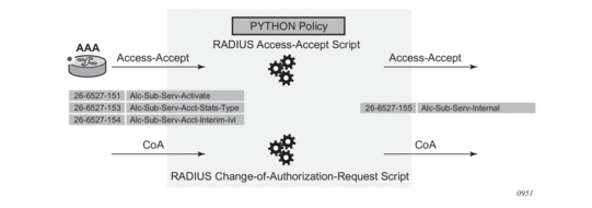
The SR OS only requires the Alc-Sub-Serv-Internal VSA [26-6527-155] to activate or deactivate the subscriber service. Subscriber service-specific VSAs [26-6527-151..154] are available to be used in the subscriber service Python script but are ignored in the SR OS.
See the Python Script section for details on the subscriber services Python script functions and operation.
A Python script must be configured for RADIUS Access-Accept and CoA messages; for example:
The Python policy must then be applied to the radius-server-policy to pass the Access-Accept messages to the Python script and to the RADIUS server to pass the CoA messages to the Python script; for example:
9.19.1.3. Python Script
The RADIUS Access-Accept and CoA messages are passed to the configured RADIUS Python scripts. As shown in Figure 149, the function of the subscriber service Python script is to interpret the subscriber service-specific VSAs that contain the subscriber service instance parameters and to generate a new Alc-Sub-Serv-Internal VSA containing the information required to activate the actual subscriber service on the PPPoE or IPoE session.
This section covers the basics to understand the functionality of a subscriber service Python script. See the Subscriber Services Python API section for a detailed description of the alc.sub_svc Python module containing functions and data structures used to define and activate a subscriber service instance.
Figure 149: Subscriber Service Python Script Operation
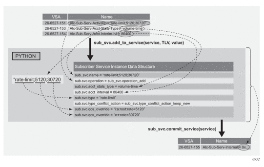
The alc.sub_svc Python module contains the required functions and data structure to commit a subscriber service, including:
- TLVs to build a data structure describing the subscriber service functionality, such as QoS overrides or PCC rules
- functions to populate the data structure such as sub_svc.add_to_service(), sub_svc.pccrule.add_to_pccrule(), and sub_svc.flow.add_to_flow()
- a function to commit the subscriber service and create the internal VSA from the data structure: sub_svc.commit_service()
9.19.1.3.1. Python Script Example
In this section an example of a Python script is explained that enables the activation or deactivation of a subscriber service.
In the example, it is assumed that only a single subscriber service is activated and/or deactivated per RADIUS message (no tagged VSAs are used) and that only a single Alc-Sub-Serv-Activate or Alc-Sub-Serv-Deactivate VSA is present (no concatenation of VSAs is required).
To change the upstream root arbiter rate and downstream aggregate rate bandwidth of an IPoE session, send the following parameters in the subscriber service activate VSA:
During the bandwidth change, the traffic should be accounted for in a separate accounting session.
To import the required modules in the Python script:
The alc.radius module provides the API access to the RADIUS VSAs in Access-Accept and CoA messages.
The alc.sub_svc module allows the API to activate and deactivate subscriber services.
The struct module is a Python module used in the example to convert data obtained from the RADIUS API as a string into Python integer values.
The following constants are used in the script:
The main flow in a subscriber service Python script is to first process the subscriber service deactivations, followed by the subscriber service activations. Optionally, the subscriber service-specific VSAs can be removed from the RADIUS message as they are not required for further processing in the SR OS:
The function to deactivate a subscriber service executes the following steps:
- checks if an Alc-Sub-Serv-Deactivate VSA [26-6527-152] is present
- if present:
- builds the subscriber service data structure. For a subscriber service deactivation, only the subscriber service instance name is required.
- commits the subscriber service deactivation
The function to activate a subscriber service executes the following steps:
- checks if an Alc-Sub-Serv-Activate VSA [26-6527-151] is present
- if present:
- separates the parameters in the attribute value with a semicolon as the delimiter. The parameters are the subscriber service type, the upstream bandwidth in kb/s, and the downstream bandwidth in kb/s.
- If the subscriber service type is rate-limit, builds the subscriber service data structure:
- specifies that the service will be added (activate)
- adds the complete attribute value as the subscriber service instance name. This name should also be used to deactivate the subscriber service.
- sets the subscriber service type and conflict action. With the conflict action set to “keep new”, if a new subscriber service of the same type is activated, the old one is deactivated first.
- configures the upstream and downstream bandwidth with a QoS override on the ingress root arbiter and egress aggregate rate
- If the subscriber service type is something else (an unknown service type), a warning is printed for debugging purposes. No action is performed in this case.
- If an Alc-Sub-Serv-Acct-Stats-Type VSA [26-6527-153] is present, adds the corresponding stats-type to the subscriber service data structure. The function also checks whether a Alc-Sub-Acct-Serv-Interim-Ivl VSA [26-6527-154] is present and adds the interval to the subscriber service data structure.Both the stats-type and interim interval must be specified as integers in the subscriber service data structure. As the RADIUS API returns an octet string, a conversion is required. The struct.unpack() function is used for this purpose.
- commits the subscriber service activation
The result of the sub_svc.commit_service() function is an Alc-Sub-Serv-Internal VSA [26-6527-155] that contains the required data for the SR OS to activate the corresponding subscriber services.
9.19.1.4. Subscriber Service Instance Activation or Deactivation with Optional RADIUS Accounting
When the SR OS receives an Alc-Sub-Serv-Internal VSA [26-6527-155] in an Access-Accept or CoA message as a result of the Python script sub_svc.commit_service() function, the corresponding subscriber services are activated and/or deactivated. Optionally, an accounting session can be started for each subscriber service instance.
The following is an example of the show service sub-services command.
The following rules apply for a subscriber service instance.
- A subscriber service instance can be activated on a:
- single-stack or dual-stack PPPoE session
- single-stack or dual-stack IPoE session
- single-stack IPoEv4 host
- A subscriber service instance is uniquely identified by its name. To deactivate a subscriber service instance, the subscriber service name must be referenced.
- A subscriber service cannot be modified. To update a subscriber service instance, the old subscriber service must be deactivated and a new one activated.
- Multiple subscriber services can be activated or deactivated in a single Access-Accept or CoA message. Tagged subscriber service-specific VSAs are available for this purpose.
- A single subscriber service instance can have multiple actions, such as multiple QoS overrides and/or multiple PCC rules.
- The conflict action determines the behavior when multiple subscriber services of the same type are activated for the same PPPoE or IPoE session:
- Conflict action = noneMultiple instances of the same type can be activated.
- Conflict action = keep newOnly a single subscriber service instance of the same type is allowed.When a new subscriber service instance of the same type is activated on a single PPPoE or IPoE session, the old instance is deactivated and the new subscriber service instance is activated.
- Conflict action = keep oldOnly a single subscriber service instance of the same type is allowed.When a subscriber service instance of the same type is activated on a single PPPoE or IPoE session, the new subscriber service instance is rejected.
- Multi-Chassis Synchronization (MCS) is not supported for subscriber services.
9.19.2. Subscriber Services RADIUS VSAs
Subscriber services VSAs 26-6527-151..154 are used as inputs for the subscriber service Python script and are ignored by the SR OS.
The subscriber service VSAs can be tagged to allow activation and deactivation of multiple subscriber service instances with a single RADIUS Access-Accept or CoA message.
Table 70 lists the subscriber services RADIUS VSAs. See the RADIUS Attributes Reference Guide for a complete description of the subscriber services VSAs.
Table 70: Subscriber Services RADIUS VSAs
Attribute ID | Attribute Name | Description |
26-6527-151 | Alc-Sub-Serv-Activate(string) | Activate a subscriber service. The attribute contains parameters as input for the subscriber service Python script to define and activate a subscriber service. Multiple VSAs can be included per message if the parameter list does not fit in a single attribute. |
26-6527-152 | Alc-Sub-Serv-Deactivate(string) | Deactivate a subscriber service. The attribute contains parameters as input for the subscriber service Python script to deactivate a subscriber service. Multiple VSAs can be included per message if the parameter list does not fit in a single attribute. |
26-6527-153 | Alc-Sub-Serv-Acct-Stats-Type(integer) | Enable or disable subscriber service accounting and specify the statistics type: volume and time or time only. Values: 1=off, 2=volume-time and 3=time |
26-6527-154 | Alc-Sub-Serv-Acct-Interim-Ivl(integer) | The interim accounting interval in seconds at which Acct-Interim-Update messages should be generated for subscriber service accounting. A value of 0 (zero) corresponds to no interim update messages. The maximum value is 300 seconds (values 1 to 300). |
26-6527-155 | Alc-Sub-Serv-Internal | For internal use only. Its value is the result of the subscriber service commit function in Python. (sub_svc.commit_service). |
9.19.3. Subscriber Service RADIUS Accounting
The configuration for subscriber service instance accounting sessions is obtained from the RADIUS accounting policies configured in the subscriber profile of the parent subscriber:
- The accounting destinations: RADIUS server configurationSubscriber service instance accounting is sent to multiple destinations when multiple RADIUS accounting policies are configured (for example, config>subscr-mgmt>sub-prof# radius-accounting policy acct-policy-1 acct-policy-2)
- The accounting attributes (include-radius-attribute) with some exceptions.Standard accounting attributes are always used for volume accounting, regardless of the configuration in the RADIUS accounting policy.An untagged [26-6527-151] Alc-Sub-Serv-Activate attribute is included in all subscriber service instance accounting messages. Its value is the subscriber service instance name (alc.sub_svc.name).
- Accounting interim updates for subscriber service instance accounting are controlled independently from the parent subscriber accounting session:
- Enabling accounting interim updates for a subscriber service instance is achieved by setting the sub_svc.acct_interval TLV in the subscriber services Python script to a value greater than 0: sub_svc.add_to_service(service, sub_svc.acct_interval, 3600)
- Disabling accounting interim updates for a subscriber service instance is achieved by setting the sub_svc.acct_interval TLV in the subscriber services Python script to 0: sub_svc.add_to_service(service, sub_svc.acct_interval, 0)
If the parent subscriber has no RADIUS accounting policy configured, subscriber service instance accounting cannot be enabled.
If the parent subscriber has a RADIUS accounting policy configured, subscriber service instance accounting can be disabled by setting the sub_svc.acct_stats_type TLV in the subscriber service Python script to 1 (Off):
Each subscriber service instance has a unique accounting session ID included as [44] Acct-Session-Id. The [50] Acct-Multi-Session-Id contains the accounting session ID of the parent PPPoE or IPoE session as shown in Table 71:
Table 71: Subscriber Service Accounting Multi-Session ID
Subscriber Service Parent | [50] Acct-Multi-Session-Id |
PPPoE session | Session Acct-Session-Id of the PPPoE session: show service id <service-id> pppoe session detail |
IPoE session | Session Acct-Session-Id of the IPoE session: show service id <service-id> ipoe session detail |
IPoEv4 host | Host Acct-Session-Id of the IPoEv4 host: show service id <service-id> subscriber-hosts detail |
The content of the volume counters when the subscriber service accounting statistics type equals volume-time is determined by the subscriber service action. For details, see the subscriber service sections that follow.
9.19.4. Accounting-Only Subscriber Service
An accounting-only subscriber service has no specific action such as qos-override or pccrule defined and has subscriber service instance accounting enabled.
An example of when an accounting-only subscriber service would be used is if additional accounting data is needed for a specific time period in the lifetime of a PPPoE or IPoE session.
The sub_svc.acct_stats_type TLV in the subscriber services Python script must be set to a value different from 1 (Off) to enable subscriber service instance accounting. For example:
The volume counters for subscriber service statistics type volume-time contain the aggregate forwarded octets and packets of the parent PPPoE or IPoE session sla-profile instance since the start of the subscriber service.
9.19.5. QoS Override-based Subscriber Service
A subscriber service instance with a qos-override action overrides queue/policer parameters (CIR, PIR, CBS, MBS) configured at the sla-profile level and hierarchical QoS parameters (aggregate rate, scheduler rate, or root arbiter rate) configured at the sub-profile level.
An example of when a QoS override-based subscriber service would be used is to temporarily offer higher bandwidth and charge for the volume consumed during this period. Figure 150 shows the volume statistics that are reported for the PPPoE or IPoE session accounting and for each of the subscriber service instances accounting sessions that were activated and deactivated.
Figure 150: Sample Use Case: QoS Override-based Subscriber Services
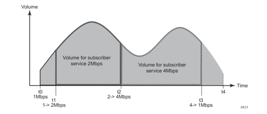
- At t0, a subscriber connects and starts consuming bandwidth at the subscriber base egress rate of 1 Mb/s. An accounting session is started for the subscriber.
- At t1, a QoS override-based subscriber service instance is activated that boosts the download bandwidth to 2 Mb/s. A 2 Mb/s QoS override-based subscriber service instance accounting session is started.
- At t2, the 2 Mb/s QoS override-based subscriber service instance is deactivated and replaced with a new one that increases the download bandwidth to 4 Mb/s. The 2 Mb/s QoS override-based subscriber service accounting session is terminated, reporting the volume consumed during t1 to t2. A new 4 Mb/s QoS override-based subscriber service accounting session is started.
- At t3, the 4 Mb/s QoS override-based subscriber service instance is deactivated. The download bandwidth is reduced to the 1 Mb/s base rate again. The 4 Mb/s QoS override-based subscriber service accounting session is terminated, reporting the volume consumed during t2 to t3.
- At t4, the subscriber disconnects. The accounting session for the subscriber is terminated, reporting the volume consumed during t0 to t4.
The sub_svc.qos_override TLV in the subscriber services Python script adds a qos-override action. For example:
Actual values are used to populate the subscriber service data structure in this example; typically, these values are sent as parameters in subscriber service-specific VSAs.
Although a QoS override-based subscriber service instance is activated for a PPPoE or IPoE session, the overrides are applied at the SLA profile instance and/or subscriber level.
QoS override-based subscriber services have precedence over dynamic QoS overrides (RADIUS Alc-Subscriber-QoS-Override VSA or Gx Charging-Rule-Definition with QoS-Information) on the PPPoE or IPoE session.
- When a dynamic QoS override such as via the Alc-Subscriber-QoS-Override VSA is active on the parent PPPoE or IPoE session and a QoS override-based subscriber service is activated, the action from the QoS override-based subscriber service is installed. When the QoS override-based subscriber service is later deactivated, the original dynamic QoS override is restored.
- When a dynamic QoS override such as via the Alc-Subscriber-QoS-Override VSA is received for a parent PPPoE or IPoE session with an active QoS override-based subscriber service, the QoS override-based subscriber service remains installed. If the QoS override-based subscriber service is later deactivated, the previously received dynamic QoS override is installed.
- When both a QoS override-based subscriber service activation and a dynamic QoS override such as via the Alc-Subscriber-QoS-Override VSA is received in a single message for the parent PPPoE or IPoE session, the QoS override-based subscriber service action is installed and the dynamic QoS override is stored for later reference. When the QoS subscriber service is later deactivated, the previously received dynamic QoS override is installed.
The installed QoS override actions can be verified in the output of the show service active-subscribers detail CLI command.
The volume counters for subscriber service statistics type volume-time contain the aggregate forwarded octets and packets of the parent PPPoE or IPoE session sla-profile instance since the start of the subscriber service.
QoS override-based subscriber services are stored in the subscriber-mgmt persistency file.
9.19.6. PCC Rule-based Subscriber Services
Policy and Charging Control (PCC) rules are defined in the 3GPP PCC architecture and used in the Diameter Gx application as a collection of parameters that enable IP traffic flows to be identified, QoS parameters and filtering actions to be applied to these flows, and charging to be performed on them. The use of PCC rules in policy management via the Diameter Gx interface is described in the PCC Rules section in the Policy Management via Gx Interface chapter.
The same PCC rule construct is used in RADIUS subscriber services to enable IP flow-based actions and accounting.
- Identify IP flows based on 5-tuple (protocol, source and destination IP address, source and destination port) and/or DSCP value.
- Apply QoS actions to these flows, such as rate limiting or change of forwarding class.
- Apply filter actions to these flows, such as forward, drop, HTTP redirect, redirect to a next hop or routing instance.
- Enable RADIUS accounting to report the forwarded octets and packets of the IP flows.
IP flow-based accounting is one use for a subscriber service using PCC rules. Activated via a self-service portal or as part of an Internet subscription package, applications identified by a 5-tuple receive specific treatment, such as bandwidth increase, expedited forwarding, or zero rating. Volume and time statistics for the application data are available in the subscriber service RADIUS accounting session. This is shown in Figure 151.
Figure 151: Example: PCC Rule-based Subscriber Service
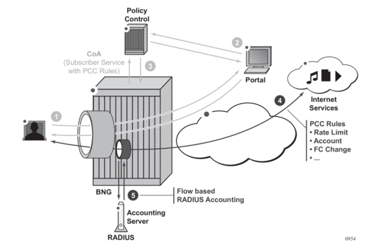
- The user subscribes to a service via a web portal.
- The policy control is informed of the new subscription.
- The policy control instructs the BNG via RADIUS to activate a subscriber service with PCC rules.
- The subscriber service is instantiated on the BNG. A dynamic policer is spawned to optionally rate-limit and/or count the application traffic.
- The subscriber service instance accounting session reports the volume of traffic forwarded as part of this service.
9.19.6.1. PCC Rule Actions
A PCC rule is a unidirectional set of IP flows sharing a same set of actions. IPv4 and IPv6 flows can be combined within the same PCC rule.
A PCC rule name must be unique for each rule applied on a single PPPoE or IPoE session. For optimal PCC rule sharing, it is recommended that the same PCC rule name be used when its content is the same (that is, the same set of flows and same set of actions).
An IP flow is identified by a combination of:
- 5-tuple (IPv4 or IPv6): src-ip, src-port, dst-ip, dst-ip, protocol/next-header
- DSCP value
The CLI equivalent is:
Supported actions include: forward, drop, redirect to ip next hop, redirect to a routing instance, HTTP redirect, forwarding class change, rate-limit, and account.
With a specified set of actions, PCC rules are instantiated in the SR OS via IP criteria or IPv6 criteria entries in SAP ingress or SAP egress QoS polices and/or in IP or IPv6 filter entries. A PCC rule precedence value determines the relative order of different PCC rules when inserted in the QoS or filter policy: a rule with a lower precedence value will be applied before a rule with a higher precedence value. Rules with the same precedence can be automatically optimized; the relative order in which they are applied is determined by the system for optimal sharing. Rules with no precedence are applied at the end and are also automatically optimized.
Table 72 and Table 73 provide an overview of the PCC rule actions and where they apply.
Table 72: Subscriber Service PCC Rule Actions Resulting in QoS Policy Changes
Action | Direction | Description |
Forwarding Class (FC) change | Ingress/Egress | changes the QoS forwarding class CLI equivalent: config>qos sap-ingress | sap-egress <id> create ip-criteria | ipv6-criteria entry <id> create match <5-tuple | dscp> exit action fc <fc> exit exit |
Rate-limit (PIR/CIR) | Ingress/Egress | rate-limit traffic matching the specified flows
The forwarded octets and packets statistics of the dynamic policer are included in subscriber service accounting. CLI equivalent: config>qos sap-ingress | sap-egress <id> create policer 1 # dynamic policer rate <pir> cir <cir> exit ip-criteria | ipv6-criteria entry <id> create match <5-tuple | dscp> exit action policer 1 exit exit |
Account | Ingress / Egress | counts traffic matching the specified flows:
The forwarded octets and packets statistics of the dynamic policer are included in subscriber service accounting. CLI equivalent: config>qos sap-ingress | sap-egress <id> create policer 1 # dynamic policer rate max cir max exit ip-criteria | ipv6-criteria entry <id> create match <5-tuple | dscp> exit action policer 1 exit exit |
Forward | Ingress/Egress | Creates an entry in the QoS policy to forward the traffic without explicit QoS action. Matching traffic will not match on the next entry (match and exit behavior). In case of overlapping flows, such as account all traffic except flow 1 and flow 2, the more specific flows must be explicitly forwarded. CLI equivalent: config>qos sap-ingress | sap-egress <id> create ip-criteria | ipv6-criteria entry <id> create match <5-tuple | dscp> exit action exit exit |
Table 73: Subscriber Service PCC Rule Actions Resulting in Filter Changes
Action | Direction | Description |
Forward/Drop | Ingress/Egress | creates a filter entry to forward or drop the trafficCLI equivalent: config>filter ip-filter | ipv6-filter <id> create entry <id> create match <5-tuple | dscp> exit action forward | drop exit exit exit |
Redirect to an IP next-hop | Ingress | redirect the traffic to the specified IP next-hop CLI equivalent: config>filter ip-filter | ipv6-filter <id> create entry <id> create match <5-tuple | dscp> exit action forward next-hop <ip-address> exit exit exit |
Redirect to a routing instance | Ingress | redirect the traffic to the specified routing instance CLI equivalent: config>filter ip-filter | ipv6-filter <id> create entry <id> create match <5-tuple | dscp> exit action forward router <router-instance> exit exit exit |
HTTP redirect | Ingress | HTTP redirection to the specified URL CLI equivalent: config>filter ip-filter | ipv6-filter <id> create entry <id> create match <5-tuple | dscp> exit action http-redirect <rdr-url-string> exit exit exit |
Figure 152 and Figure 153 show the actions that can be combined in a single ingress or egress PCC rule.
Figure 152: Supported Combinations of Ingress PCC Rule Actions
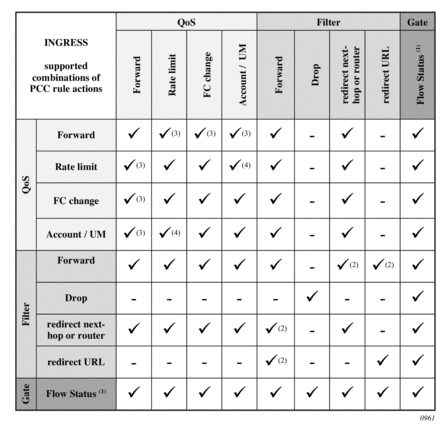
Figure 153: Supported Combinations of Egress PCC Rule Actions
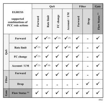
Notes:
- The Flow Status can only be set via Gx.For RADIUS subscriber service-based PCC rules, the Flow Status is fixed to Enabled.
- The filter action forward is ignored (not installed) when combined with the following filter actions: redirect next-hop, redirect router, or http-redirect.
- The QoS action forward is ignored (not installed) when combined with the following QoS actions: rate-limit, FC change, account/Usage Monitoring (UM).
- When the QoS action rate-limit and QoS action account or Usage Monitoring (UM) are combined, only a single dynamic policer is installed, which is used for both rate-limiting and obtaining forward statistics for accounting or usage monitoring.
9.19.6.2. PCC Rule Instantiation
A PCC rule can result in one or more IPv4/IPv6 filter and/or QoS policy IPv4/IPv6 criteria entries. This is transparent to the operator.
- A PCC rule is split into IPv4 filter entries, IPv6 filter entries, SAP ingress QoS IP or IPv6 criteria, and SAP egress QoS IP or IPv6 criteria. See Figure 208.
- Each entry is inserted into the corresponding policy at a reserved range for dynamic PCC rule inserts. See Figure 209. Within the reserved range, the (optional) precedence value for the rule is taken into account for the relative order of different PCC rules.
- The QoS rate-limit and account actions will spawn a dynamic policer from a reserved range in the QoS policy. A template configuration provides dynamic policer parameters such as hierarchical policing parent, burst sizes (MBS, CBS), statistics mode and packet byte offset. A maximum of one dynamic policer is instantiated per PCC rule. There is a maximum of 63 dynamic policers per direction and per SLA profile instance. The output queue for PCC rule traffic mapped in the dynamic policer is determined by a mechanism called forwarding class inheritance: the output queue is the same queue that would be used if a packet with the same forwarding class as the PCC rule packet was classified using the applied QoS policy. The resulting output queue can be a local subscriber queue (when the FC is mapped to a queue or when the FC is mapped to a policer at egress and the policer is mapped to a local queue), a shared queue (when the FC is mapped to a policer at ingress) or a queue-group queue (when the FC is mapped to a policer at egress).
- Optimal policy and rule sharing is achieved via QoS and filter policy cloning and internal PCC rule optimizations. The mechanisms are the same as for Gx-initiated PCC rules as described in the Generic Policy Sharing and Rule Sharing and Gx Rule Ordering sections of the Diameter and Diameter Applications chapter.PCC rule sharing can only happen when the content is the same: identical name, direction, precedence value, set of flows, and set of actions. PCC rules with the same content will have the same PCC rule ID.Filter and QoS policy clones that result from PCC rule instantiation can be recognized by a filter ID or QoS policy ID in the format 1 to 65535:P1 to 4096; for example, filter ip 10:p3
- PCC rules can be inactive if the corresponding host type is not present. For example, a PCC rule-based subscriber service with an IPv6 filter action can be activated on an IPoE session while there is no IPv6 host instantiated on the session. When the IPv6 host is later created, the PCC rule is activated.
The following initial configuration is required prior to activating PCC rule-based subscriber services.
- To install PCC rule QoS actions, a non-default ingress and egress QoS policy with a sub-insert-shared-pccrule range configured must be associated with the IPoE or PPPoE session (the default QoS policy cannot be modified). If a rate-limit or account action is needed, a dynamic policer range must also be configured. Additional dynamic policer parameters are optional.configure qos sap-ingress <policy-id> create sub-insert-shared-pccrule start-entry <entry-id> count <count> dynamic-policer range start-entry <policer-id> count <count> packet-byte-offset {add <add-bytes> | subtract <sub-bytes>} mbs <size> [bytes|kilobytes] cbs <size> [bytes|kilobytes] parent <arbiter-name> [weight <weight-level>] [level <level>] stat-mode <stat-mode> exit exit
- To install PCC rule filter actions, an IPv4 and/or IPv6 filter with sub-insert-shared-pccrule range configured must be associated with the IPoE or PPPoE session.
Although a PCC rule-based subscriber service is activated on a PPPoE or IPoE session, the actions are applied at the SLA profile instance and/or subscriber host level.
- PCC rule QoS actions result in QoS policy clones that are applied at the SLA profile instance level. Traffic from all subscriber hosts and sessions sharing the SLA profile instance will be subject to the specified actions.
- PCC rule filter actions result in IPv4 or IPv6 filter clones that are applied at the subscriber host level. Only traffic from the subscriber host of the same type (IPv4 or IPv6) that belongs to the PPPoE or IPoE session will be subject to the specified actions.
A PCC rule with flow match criteria that are not explicitly IPv4 or IPv6 results in both IPv4 and IPv6 match criteria being installed; for example, destination address = any.
Filter actions are executed before QoS actions. If an IP flow is rate-limited, it should pass the IPv4 or IPv6 filter first. Adding a QoS action rate limit to a PCC rule will not automatically insert a corresponding forward entry in an IP filter. When needed, this must be done explicitly by the operator with a filter forward action. For example, an IP filter with the default action drop and a number of explicit forward entries is applied to an IPoE session. A new IP flow must be rate-limited and accounted for. The PCC rule should include match criteria for the IP flow and a QoS action rate limit, QoS action account, and filter action forward. Without the filter action forward, the IP flow would be dropped by the default action in the filter policy.
9.19.6.3. PCC Rules in a Subscriber Service
The example below shows a pseudo-language representation of PCC rules in a subscriber service.
- A subscriber service can contain multiple PCC rules. Because a PCC rule is unidirectional, including an ingress and an egress PCC rule enables subscriber service accounting of bidirectional flows.
- A PCC rule can contain multiple flows. Flows in a PCC rule can be a mix of IPv4 and IPv6 flows.
The sub_svc.pccrule TLV in the subscriber services Python script adds a PCC rule to the subscriber service, as shown in the output example below:
Actual values are used to populate the subscriber service data structure in this example; typically, these values are sent as parameters in subscriber service-specific VSAs.
In the above subscriber service example, two PCC rules are installed, each with one flow:
- pcc-rule-1-i: ingress traffic to destination 10.1.1.0/24 is rate-limited to 1 Mb/s
- pcc-rule-1-e: egress traffic from 10.1.1.0/24 is rate-limited to 5 Mb/s
Subscriber service instance volume-time accounting is enabled. The volume counters include the forwarded octets and packets of the dynamic policers installed for the above rules and count the traffic matching the flows.
The counters reported in PCC rule-based subscriber services RADIUS accounting are determined by the PCC rule QoS account action.
- If at least one PCC rule in the subscriber service has the QoS account action enabled (pccrule.qos_action_account = True), then the volume counters contain the sum of the dynamic policer forwarded octets and packets statistics of all the PCC rules in the subscriber service with pccrule.qos_action_account = True.
- If all PCC rules in the subscriber service have the QoS account action disabled (pccrule.qos_action_account = False), then the volume counters contain the aggregated forwarded octets and packets of the parent PPPoE or IPoE session SLA profile instance since the start of the subscriber service.
PCC rule-based subscriber services are not stored in the subscriber-mgmt persistency file.
9.19.6.4. Interaction of the PPPoE or IPoE Session QoS Model and PCC Rule-based Subscriber Services
PCC rule-based subscriber services with QoS actions interact with the classification and QoS forwarding mechanisms. This section describes how this affects the parent RADIUS accounting volume counters.
For subscriber service PCC rule QoS actions that do not result in the instantiation of a dynamic policer (such as a change of forwarding class or forward), the PCC rule matched traffic is included in the parent accounting session volume counters. This is shown in Figure 154, where the forwarding class is mapped to a subscriber queue, and in Figure 155 where the forwarding class is mapped to a subscriber policer.
Figure 154: PCC Rule-based Subscriber Service—QoS Interaction: No Dynamic Policer, FC ® Queue

Figure 155: PCC Rule-based Subscriber Service—QoS Interaction: No Dynamic Policer, FC ® Policer ® Queue-group
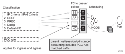
For subscriber service PCC rule QoS actions that result in the instantiation of a dynamic policer (such as rate-limit or account), the dynamic policer counters are not included in the aggregate counters nor are they reported as separate detailed policer statistics. Instead, the traffic matching the PCC rules is counted in the output queues that correspond to the forwarding class of the packets.
- On ingress, the dynamic policer PCC rule traffic is never included in the parent host, session, or queue instance accounting session counters. Ingress policed traffic always uses the ingress shared policer output queues, as shown in Figure 156.
Figure 156: PCC Rule-based Subscriber Service—QoS Interaction: Dynamic Policer ® Ingress Shared Policer Output Queues

- To include the egress dynamic policer PCC rule traffic in the parent host, session, or queue instance accounting session counters, the dynamic policer must use a local subscriber output queue, as shown in Figure 157.
Figure 157: PCC Rule-based Subscriber Service—QoS Interaction: Dynamic Policer, FC ® Queue (Egress)

- To exclude the egress dynamic policer PCC rule traffic from the parent host, session, or queue instance accounting session counters, the dynamic policer must use a queue-group output queue, as shown in Figure 158. The dynamic policer traffic inherits the policer-to-output queue mapping from the static policer that corresponds to the forwarding class of the packet. The following SAP egress configuration example uses the default policer output queue-group:config>qos sap-egress 10 create sub-insert-shared-pccrule start-entry 200 count 10 dynamic-policer range start-entry 10 count 10 exit policer 1 create exit fc be create policer 1 exit exitIf a packet is classified as FC = Best Effort (BE) and matches a PCC rule with rate-limit action only (no FC change), the traffic will hit the PCC rule dynamic policer and then the queue-group queue associated with policer 1 (the static policer for FC = BE).
Figure 158: PCC Rule-based Subscriber Service—QoS Interaction: Dynamic Policer, FC ® Policer ® Policer Output Queues (Egress)

- A special case occurs when, at egress, the forwarding class maps to a static policer and then to a local subscriber queue. Traffic for that forwarding class hitting a dynamic policer will use the local subscriber queue as the output queue. In this case, the dynamic policer PCC rule traffic is included in the parent host, sessions or queue instance accounting session counters. This is shown in Figure 159.
Figure 159: PCC Rule-based Subscriber Service—QoS Interaction: Dynamic Policer, FC ® Policer ® Local Queue (Egress)

9.19.6.5. PCC Rules on HSMDAv2
This section describes the differences in PCC rule-based subscriber services when applied to subscriber sessions terminating on an HSMDAv2 card, further referred to as HSMDA.
The activation of PCC rule-based subscriber services is explained in the previous sections.
The filter policy cloning resulting from the instantiation of PCC rule filter actions is the same on the HSMDA:
- IP or IPv6 filter policies applied at the sla-profile ingress or egress contexts can be cloned when PCC rules with filter actions are instantiated on HSMDA subscriber sessions.
The QoS policy cloning resulting from the instantiation of PCC rule QoS actions is different on HSMDAs because of the specific egress QoS architecture:
- ingress — The QoS policy applied at the sub-profile contains the active configuration and can be cloned when ingress PCC rules with QoS actions are instantiated on HSMDA subscriber sessions. When a PCC rule clone exists, the QoS policy applied at the sub-profile ingress cannot be changed.
- egress: The QoS policy applied at the sla-profile contains the active configuration except for the HSMDA queues. This QoS policy can be cloned when egress PCC rules with QoS actions are instantiated on HSMDA subscriber sessions. When a PCC rule clone exists, the QoS policy associated at the sla-profile egress cannot be changed.
The following table summarizes the configuration of HSMDA QoS and filter policies:
Table 74: HSMDA QoS and Filter Policy Configurations
SLA Profile | |
Ingress | CLI context: config>subscr-mgmt>sla-prof>ingress
|
Egress | CLI context: config>subscr-mgmt>sla-prof>ingress
|
Sub Profile | |
Ingress | CLI context: config>subscr-mgmt>sub-prof>hsmda>ingress-qos
|
Egress | CLI context: config>subscr-mgmt>sub-prof>hsmda>egress-qos
|
The following restrictions apply for PCC rule based subscriber services on HSMDA subscriber sessions:
- An egress rate limit (PIR/CIR) action is not supported. Egress dynamic policers on HSMDA are always installed with PIR=max and CIR=0. The CBS value for dynamic policers is ignored and it is recommended to keep the default MBS value.
- There is no support for hierarchical policing on egress dynamic policers. The subscriber host or session setup fails when a sub-profile is assigned containing an egress policer-control-policy configuration.
- Only a single SLA Profile Instance (SPI) can be active for a subscriber when a PCC-rule subscriber service containing egress QoS actions is active or activated:
- The activation of a PCC rule-based subscriber service containing egress QoS actions fails when more than one SPI is active for the subscriber.
- A new subscriber host or session setup fails when a new SPI is required while a PCC rule based subscriber service containing egress QoS actions is active.
- A PCC rule based subscriber service containing egress QoS actions must be removed before the SLA profile of a subscriber can be changed.
9.19.6.5.1. Interaction between PCC Rule-Based Subscriber Services and RADIUS Queue-Instance, Host or Session Accounting Volume Counters
PCC rule based subscriber services with QoS actions interact with the classification and QoS forwarding mechanisms. This section describes how this affects the parent RADIUS accounting volume counters.
For subscriber service PCC rule QoS actions that result in the instantiation of a dynamic policer (such as rate-limit or account), the dynamic policer counters are not included in the aggregate counters nor are they reported as separate detailed policer stats. Instead the traffic matching the PCC rules is counted in the output queues that correspond with the Forwarding Class of the packets:
- On ingress, the dynamic policer PCC rule traffic is never included in the parent host, session or queue-instance accounting session counters. Ingress policed traffic always uses the ingress shared policer output queues. This is the same as for non-HSMDA scenarios. See Figure 156.
- On egress, the dynamic policer PCC rule traffic is always included in the parent host, session or queue-instance accounting session counters. Egress policed traffic always uses the egress HSMDA queues as shown in Figure 160.
Figure 160: PCC Rule-Based Subscriber Service – HSMDA Egress Accounting
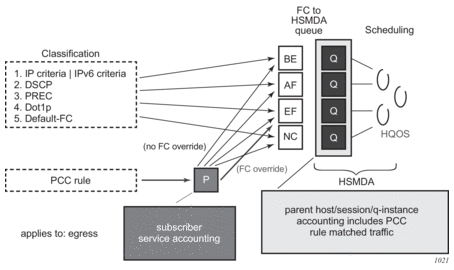
9.19.6.6. PCC Rule-based Subscriber Service Activation Failures
PCC rule-based subscriber service activation failures can be categorized as failures detected in the subscriber services Python script as runtime errors (see Table 75) and failures detected in the Enhanced Subscriber Management (ESM) processing (see Table 76).
Table 75: PCC Rule-based Subscriber Service: Python Runtime Errors
Python Runtime Errors |
Pcc rule name type must be a string |
Pcc rule name value too long |
Pcc rule qos action account value must be True(1) or False(0) |
Pcc rule filter action redirect to nexthop_v4/v6 type must be a string |
Pcc rule filter action redirect to nexthop_v4/v6 value must be a valid IPv4/v6 address |
Pcc rule filter action http redirect value is not a valid URL |
Pcc rule filter action http redirect type must be a string |
Pcc rule filter action http redirect value too long (> 255) |
Pcc rule qos action fwd class change value is invalid |
Pcc rule qos action rate limit type must be an int |
Pcc rule precedence type must be an int |
Pcc rule flow dscp match type must be a string |
Pcc rule flow dscp match value is invalid |
Pcc rule flow src/dst_ip match type must be a string: <ipv4-address>|<ipv6-address>|any |
Pcc rule flow src/dst_ip match value is not a valid IP address: <ipv4-address>|<ipv6-address>|any |
Pcc rule flow port match type must be a string: <port>[-<port>] with port [0..65535] |
Pcc rule flow protocol match type must be an int |
Pcc rule flow protocol match value must be less than 255 |
Pcc rule must have a name |
Table 76: PCC Rule-based Subscriber Service: ESM failures
ESM —RADIUS Decoding Failures |
The PCC rule precedence must be in the range 0 to 65535. |
The PCC rule name has a maximum of 100 displayable characters. |
The PCC rule redirect URL has a maximum of 255 displayable characters. |
All flows in a PCC rule must have the same direction (ingress or egress). |
A PCC rule has a maximum of 128 flows. |
A PCC rule name can occur only once in a RADIUS message. |
A flow in a PCC rule cannot have a mix of IPv4 and IPv6 addresses (for example src-ip and dst-ip). |
ESM—Processing Failures |
If a PCC rule contains a direction-specific action (such as a redirect), it must contain at least one flow in that direction. |
If a PCC rule contains only IPv4 actions (such as a redirect to an IPv4 next hop), it must contain at least one IPv4 flow. This also applies to IPv6. |
The combinations of PCC rule actions must be supported (see Figure 152 and Figure 153). |
There must be at least one flow and at least one action per PCC rule. |
There is a maximum of 64 PCC rules per host or session. |
There are not enough filter or QoS resources to create policy clones or apply them to the host or session. |
The filter or QoS policy clone cannot be created (for example, the redirect service does not exist). |
Simultaneous provisioning of PCC rules from Gx and RADIUS is operationally blocked per subscriber session/host. |
9.19.7. Combined Subscriber Services
A subscriber service instance can be built with a combination of QoS override actions and PCC rules. In this case, the reported volume counters for subscriber service statistics type volume-time are determined by the PCC rule account action, as shown in Table 77.
Table 77: Subscriber Service Accounting—Reported Volume Counters
QoS Override | PCC Rule | Reported Volume Counters |
No | No | Aggregated SLA profile queue and policer statistics |
Yes | No | Aggregated SLA profile queue and policer statistics |
No | Yes, “pccrule.qos_action_account = False” for all PCC rules | Aggregated SLA profile queue and policer statistics |
No | Yes, “pccrule.qos_action_account = True” for at least one PCC rule | Dynamic policer statistics for PCC rules with “pccrule.qos_action_account = True” |
Yes | Yes, “pccrule.qos_action_account = False” for all PCC rules | Aggregated SLA profile queue and policer statistics |
Yes | Yes, “pccrule.qos_action_account = True” for at least one PCC rule | Dynamic policer statistics for PCC rules with “pccrule.qos_action_account = True” |
9.19.8. Subscriber Services Python API
The SR OS alc.sub_svc Python module offers functions and data structures to describe, activate, and deactivate a subscriber service.
9.19.8.1. Common Subscriber Services Python API
Table 78 lists the subscriber service functions in the alc.sub_svc module.
Table 78: Subscriber Service Functions in the alc.sub_svc Module
sub_svc Functions | Description |
sub_svc.add_to_service (svc, sub_svc TLV, value) | appends a TLV to the service list. The service list describes the subscriber service and should be passed to the sub_svc.commit_service() to activate or deactivate the subscriber service. Parameters: svc (type = list): service list that describes the subscriber service. sub_svc TLVs are appended to this list with the sub_svc.add_to_service() function. sub_svc TLV (type int): TLV that will be appended to the service list value (type as defined for the sub_svc TLV): the value of the sub_svc TLV that will be appended to the service list |
sub_svc.commit_service (svc) | creates the required internal VSAs based on the TLVs provided in the svc list. Parameters: svc (type = list): service list that describes the subscriber service. sub_svc TLVs are appended to this list with the sub_svc.add_to_service() function. The service list should be passed to sub_svc.commit_service() to activate or deactivate the subscriber service. |
Table 79 lists the subscriber service TLVs in the alc.sub_svc module.
Table 79: Subscriber Service TLVs in the alc.sub_svc Module
sub_svc TLV | Activate/ Deactivate | TLV Details | |
name (string) | M/M | Purpose | The unique subscriber service instance identifier (key). This field will be matched for a subscriber service deactivate request. This field could, for example, be populated with the service-name and corresponding parameter list. This value is also echoed in the Alc-Sub-Serv-Session attribute in accounting messages. When not specified, the subscriber service activation fails and an event log is generated: WARNING: SVCMGR #2511 Base RADIUS CoA Error “Problem encountered in Subscriber Management, while processing a CoA request from a RADIUS server: Could not decode RADIUS Attribute “Sub Service””. |
Value | Free format string (max. length = 1000 bytes) | ||
Default | Empty string | ||
operation (int) | M/O | Purpose | Specifies if the referenced subscriber service should be activated or deactivated |
Value | operation_add (1): activate the subscriber service instance | ||
operation_del (2): deactivate the subscriber service instance | |||
Default | operation_del | ||
acct_stats_type (int) | O/n.a. | Purpose | Defines if RADIUS accounting should be enabled for this subscriber service instance. If enabled, the accounting mode (Time or Volume and Time) is specified. Values as defined for Alc-Sub-Serv-Acct-Interim-Ivl VSA |
Value | Off (1) | ||
Volume-time (2) | |||
Time (3) | |||
Default | Off | ||
acct_interval (int) | O/n.a. | Purpose | Defines the RADIUS interim accounting update interval for this subscriber service instance Values as defined for Alc-Sub-Serv-Acct-Interim-Ivl VSA |
Value | 0 (no interim updates) | ||
1 to 299 (rounded to a maximum 300 seconds) | |||
300 to 15552000 (override the local configured update-interval for this subscriber service instance) | |||
Default | Update interval from the parent subscriber RADIUS accounting policy | ||
type (string) | O/n.a. | Purpose | Grouping of subscriber service instances that belong to the same PPPoE or IPoE session |
Value | Free format string (max. length = 255 bytes) | ||
Default | empty string | ||
type_conflict_action (int) | O/n.a. | Purpose | Defines the action when another subscriber service instance of the same type is already activated for the same PPPoE or IPoE session. |
Value | type_conflict_action_keep_old (1): reject the new subscriber service instance | ||
type_conflict_action_keep_new (2): deactivate the old and activate the new subscriber service instance | |||
type_conflict_action_none (3): allow multiple subscriber service instances of this type | |||
Default | type_conflict_action_none | ||
- M=Mandatory, O=Optional, n.a.=ignored
Note:
9.19.8.2. Subscriber Service QoS Override Python API
Table 80 lists the QoS override TLVs in the alc.sub_svc module.
Table 80: QoS Override TLVs in the alc.sub_svc Module
sub_svc TLV | Activate/ Deactivate | TLV Details | |
qos_override (string) | O/n.a. | Purpose | Adds a QoS override to the subscriber service. Multiple qos_override TLVs can be added in a single subscriber service instance. |
Value | As defined for the RADIUS Alc-Subscriber-QoS-Override VSA [26-6527-126]. See details below. | ||
Default | Not included | ||
- M=Mandatory, O=Optional, n.a.=ignored
Note:
QoS override TLV value format:
<direction>:<QoS object>:[<id or name>:][<parameter>=value,...]
where:
<direction> = i or I for ingress
<direction> = e or E for egress
<QoS object> = q or Q for queue overrides
<QoS object> = p or P for policer overrides
<QoS object> = r or R for egress aggregate-rate overrides
<QoS object> = a or A for root arbiter overrides
<QoS object> = s or S for scheduler overrides
<id or name> = identifies the QoS object; for example, queue-id
<parameter>=value,... = a comma-separated list of parameters to override with the corresponding value
[iIeE]:[qQ]:<queue-id>:(pir=|cir=|mbs=|cbs=|wrr_weight=)
[iIeE]:[pP]:<policer-id>:(pir=|cir=|mbs=|cbs=)
[eE]:[rR]:rate=
[iIeE]:[aA]:root:rate=
[iIeE]:[sS]:<scheduler-name>:(rate=|cir=)
pir, cir and rate values must be specified in kilobits per second (kb/s)
mbs and cbs values must be specified in bytes
wrr_weight can be specified for egress queues [1..4] for hsmdsv2 only
9.19.8.3. Subscriber Service PCC Rules Python API
Table 82 lists the PCC rule PLVs in the alc.sub_svc module.
Table 81: PCC Rule TLVs in the alc.sub_svc Module
sub_svc TLV | Activate/ Deactivate | TLV Details | |
pccrule (list) | O/n.a. | Purpose | Adds a PCC rule to the subscriber service. Multiple PCC rule TLVs can be added in a single subscriber service instance. |
Value | A PCC rule list describing the PCC rule with PCC rule TLVs such as name, precedence, direction, flows, and actions PCC rule TLVs are appended to the PCC rule list with the sub_svc.pccrule.add_to_pccrule() function. | ||
Default | Not included | ||
- M=Mandatory, O=Optional, n.a.=ignored
Note:
Table 82 lists the alc.sub_svc.pccrule function.
Table 82: alc.sub_svc.pccrule Function
alc.sub_svc.pccrule Function | Description |
sub_svc.pccrule.add_to_pccrule (pccrule, pccrule TLV, value) | Appends a PCC rule TLV such as name, precedence, flow, or action to the PCC rule list. The PCC rule list describes the PCC rule and can be added to a subscriber service with the sub_svc.add_to_service() function. Parameters: pccrule (type = list): PCC rule list that describes the PCC rule. PCC rule TLVs are appended to this list with the sub_svc.pccrule.add_to_pccrule() function. pccrule TLV (type int): PCC rule TLV that will be appended to the PCC rule list value (type as defined for the PCC rule TLV): the value of the PCC rule TLV that will be appended to the PCC rule list |
Table 83 lists the PCC rules TLVs in the alc.sub_svc.pccrule module.
Table 83: PCC Rule TLVs in the alc.sub_svc.pccrule Module
PCC Rule TLV | M|O | TLV Details | |
pccrule.name (String) | M | Purpose | Specifies the name of the PCC rule A PCC rule with the same name and same or different content can only be applied once on a single parent PPPoE or IPoE session. A PCC rule with the same name and same or different content can be applied on different parent PPPoE or IPoE sessions. Rules with the same name but different content will get a different PCC rule identifier (rule id). |
Value | Free format string (maximum length = 100 bytes) | ||
Default | n/a | ||
pccrule.precedence (Integer) | O | Purpose | Specifies the precedence value for the PCC rule. The precedence defines a relative order of the different PCC rules: a rule with a lower precedence value will be applied before a rule with a higher precedence value. Rules with the same precedence and rules without precedence can be automatically optimized; the relative order in which they are applied is determined by the system for optimal sharing. |
Value | 0 to 65535 | ||
Default | n/a These rules are applied at the end. | ||
pccrule.direction (Integer) | M | Purpose | Specifies the direction of the PCC rule: ingress or egress |
Value | direction_ingress (1) | ||
direction_egress (2) | |||
Default | n/a | ||
pccrule.flow (list) | M | Purpose | Adds a flow to the PCC rule. At least one flow must be added to a PCC rule. Multiple flow TLVs can be added to a PCC rule. |
Value | A flow list describing the flow with flow TLVs such as dscp, protocol, src-ip, dst-ip, src-port, and dts-port Flow TLVs are appended to the flow list with the sub_svc.flow.add_to_flow() function. | ||
Default | Not included | ||
pccrule.qos_action_ account (Boolean) | O (1) | Purpose | PCC rule action: account Can be applied on ingress and egress Results in IPv4 and/or IPv6 criteria entry in QoS policies. When set to True: if no rate-limit action is specified, a dynamic policer with pir=cir=max is instantiated for all flows in the PCC rule CLI equivalent: policer 1 # dynamic policer rate max cir max exit entry 10 create match … exit action policer 1 exit The forwarded octets and packets statistics of the dynamic policer associated with this PCC rule are included in subscriber service accounting. |
Value | True (1) | ||
False (0) | |||
Default | False | ||
pccrule.qos_action_ change_fc (string) | O (1) | Purpose | PCC rule action: change the forwarding class Can be applied on ingress and egress. Results in IPv4 and/or IPv6 criteria entry in QoS policies CLI equivalent: entry 10 create match … exit action fc <fc-name> exit |
Value | String with fixed format forwarding class name: “be”, “l2”, “af”, “l1”, “h2”, “ef”, “h1” or “nc” | ||
Default | n/a | ||
pccrule.qos_action_ rate_limit_cir (Integer) | O (1) | Purpose | PCC rule action: rate-limit CIR
Can be applied on ingress and egress. Results in IPv4 and/or IPv6 criteria entry in QoS policies CLI equivalent: policer 1 # dynamic policer rate … cir <cir> exit entry 10 create match … exit action policer 1 exit |
Value | 0 to 2000000000 kb/s | ||
Default | n/a | ||
pccrule.qos_action_ rate_limit_pir (integer) | O (1) | Purpose | PCC rule action: rate-limit PIR
Can be applied on ingress and egress. Results in IPv4 and/or IPv6 criteria entry in QoS policies. CLI equivalent: policer 1 # dynamic policer rate <pir> exit entry 10 create match … exit action policer 1 exit |
Value | 1 to 2000000000 kb/s | ||
Default | None | ||
pccrule.qos_action (integer) | O (1) | Purpose | PCC rule action: QoS forward Can be applied on ingress and egress Results in IPv4 and/or IPv6 criteria entry in QoS policies CLI equivalent: entry 10 create match … exit action exit |
Value | pccrule.qos_action_forward (1) | ||
Default | n/a | ||
pccrule.filter_action_http_redirect (string) | O (1) | Purpose | PCC rule action: http-redirect Can be applied on ingress only Results in an IPv4 and/or IPv6 filter entry CLI equivalent: entry 10 create match next-header tcp ... exit action http-redirect <rdr-url-string> exit exit |
Value | http-redirect URL string (maximum 255 characters) | ||
Default | n/a | ||
pccrule.filter_action_ redirect_to_nexthop_v4 (string) | O (1) | Purpose | PCC rule action: redirect to a next-hop IPv4 address Can be applied on ingress only Results in an IPv4 filter entry CLI equivalent: entry 10 create match ... exit action forward next-hop <ip-address> exit exit |
Value | IPv4 address | ||
Default | n/a | ||
pccrule.filter_action_ redirect_to_nexthop_v6 (string) | O (1) | Purpose | PCC rule action: redirect to a next-hop IPv6 address Can be applied on ingress only Results in an IPv6 filter entry. CLI equivalent: entry 10 create match ... exit action forward next-hop <ipv6-address> exit exit |
Value | IPv6 address | ||
Default | None | ||
pccrule.filter_action_ redirect_to_router_v4 (integer) | O (1) | Purpose | PCC rule action: redirect to a routing instance Can be applied on ingress only Results in an IPv4 filter entry CLI equivalent: entry 10 create match ... exit action forward router <router-instance> exit exit |
Value | service-id | ||
Default | n/a | ||
pccrule.filter_action_ redirect_to_router_v6 (Integer) | O (1) | Purpose | PCC rule action: redirect to a routing instance Can be applied on ingress only Results in an IPv6 filter entry CLI equivalent: entry 10 create match ... exit action forward router <router-instance> exit exit |
Value | service-id | ||
Default | n/a | ||
pccrule.filter_action (Integer) | O (1) | Purpose | PCC rule action: Filter forward or drop Can be applied on ingress and egress Results in an IPv4 and/or IPv6 filter entry CLI equivalent: entry 10 create match ... exit action forward | drop exit exit |
Value | pccrule.filter_action_forward (1) | ||
pccrule.filter_action_drop (2) | |||
Default | n/a | ||
- (1) At least one PCC rule action must be specified.
- M=Mandatory, O=Optional
Notes:
Table 84 lists the alc.sub_svc.flow function.
Table 84: alc.sub_svc.flow Functions
alc.sub_svc.flow Functions | Description |
sub_svc.flow.add_to_flow (flow, flow TLV, value) | Appends a flow TLV such as dscp, protocol, src-ip, dst-ip, src-port, or dst-port to the flow list. The flow list defines matching criteria for an IP flow and can be added to a PCC rule with the sub_svc.pccrule.add_to_pccrule() function. Parameters: flow (type = list): list containing the match criteria (DSP, 5-tuple) that describes an IP flow. Flow TLVs are appended to this list with the sub_svc.flow.add_to_flow() function. The flow is added to a PCC rule with the sub_svc.pccrule.add_to_pccrule() function. flow TLV (type int): Flow TLV that will be appended to the flow list. value (type as defined for the flow TLV): the value of the flow TLV that will be appended to the flow list |
Table 85 lists the PCC Rule TLVs alc.sub_svc.flow Module.
Table 85: PCC Rule TLVs alc.sub_svc.flow Module
Flow TLV | M|O | TLV Details | |
flow.dscp (string) | O | Purpose | Specifies a DSCP flow match criterion |
Value | Fixed DSCP name strings as in the output of show qos dscp-table; for example, “be” or “ef”. The DSCP name must be specified in lower case. | ||
Default | n/a | ||
flow.protocol (integer) | O | Purpose | Specifies a protocol number match criterion |
Value | 0 to 255 | ||
Default | n/a | ||
flow.dst-ip (string) | O | Purpose | Specify a destination IPv4 or IPv6 match criterion |
Value | ipv4-address | ipv6-address | any where ipv4-address: d.d.d.d[/m] d [0 to 255] m [0 to 32] ipv6-address: x:x:x:x:x:x:x:x[/preflen] x: [0 to FFFF] preflen: 0 to 128 | ||
Default | any | ||
flow.dst-port (string) | O | Purpose | Specify a destination port match criterion |
Value | port or port range: port[-port] where port: 0 to 65535 | ||
Default | n/a | ||
flow.src-ip (string) | O | Purpose | Specify a source IP or IPv6 match criterion |
Value | ipv4-address | ipv6-address | any where ipv4-address: d.d.d.d[/m] d [0 to 255] m [0 to 2] ipv6-address: x:x:x:x:x:x:x:x[/preflen] x: [0 to FFFF] preflen: 0 to 128 | ||
Default | any | ||
flow.src-port (string) | O | Purpose | Specifies a source port match criterion |
Value | port or port range: port[-port] where port: 0 to 65535 | ||
Default | n/a | ||
9.19.9. Operational Commands
9.19.9.1. Show Commands
To display the active subscriber services in the system, use the show service sub-services CLI command. The sub-service-name filter is a longest match.
Sample output:
To display the active PCC rules in the system, use the show service active-subscribers pcc-rule CLI command. A PCC rule can be inactive when, for example, a PCC rule with filter actions on IPv6 flows is activated on an IPv4single-stack PPPoE or IPoE session.
Sample output:
Use the following alternative command to check the PCC rules in the system:
The statistics of dynamic policers can be displayed with:
The details of the cloned QoS and filter policies as a result of PCC rule activation can be displayed with the following show commands:
9.19.9.2. Debug Commands
There are no specific RADIUS subscriber services debug commands. The debugging is part of the RADIUS and Python debug output; for example:
9.19.9.3. Resource Monitoring
For information on resource monitoring, see the PCC Rules and Capacity Planning and PCC Rule Scaling Example sections in the Diameter and Diameter Applications chapter.
The following CLI command provides an overview of the resource usage per line card, such as the number of ACL and ACL QoS entries, Filters, QoS policies, dynamic policers, and QoS overrides:
These resource counters are available in SNMP and can be used in RMON to trigger threshold crossing alarms; for example:
The summary output of the show subscriber-mgmt pcc-rule command lists the number of active PCC rules and the number of active combinations:
9.20. Residential Gateway Replacement
Residential gateway (RG) replacements are performed for a variety of reasons such as upgrading hardware, replacing broken equipment, or relocating to a new home. However, the BNG’s anti-spoof filter and host-limit features can sometime prevent immediate RG replacement. In some cases, a subscriber must wait for an old DHCP lease to expire before a new RG is allowed to connect to the BNG. For example, some service providers assign an IP address and/or prefix based on physical line, SAP-id, circuit-id, or interface-id. Therefore, a home is always assigned the same IP address and/or prefix. On the BNG, an anti-spoof mechanism prevents different MAC addresses from using the same IP address. As a result, the new RG fails the anti-spoof filter and is denied an IP address and/or prefix. The subscriber in this case must wait for the DHCP lease of the RG to time out in order for the anti-spoof filter to remove its entry.
Two features, lease-override and shcv-policy, may help improve the RG replacement process. These features focus on minimizing service interruption and enhancing the end subscriber experience. RGs, in general, have no mechanisms to inform the BNG or the DHCP server that they have been disconnected from the network. Even if the BNG has periodic SHCV enabled, the detection might take some time. Often, when a subscriber plugs in a new RG, the BNG still has the old RG registered as a host. This has two consequences. First, if the new RG is assigned the same IP address as the old RG, then an IP-conflict occurs and fails the anti-spoof filter. Second, if the SAP has a host limit or a session limit provisioned, then exceeding the limit will prevent the new RG from receiving an IP address and/or prefix.
Starting in Release 13.0R4, if an IP conflict occurs on the same SAP, then by default the new RG (MAC) will immediately override the DHCP lease of the old device. This is known as lease-override. This is applicable to DHCP relay and proxy for both IPv4 and IPv6 hosts. Prior to 13R4, lease-override only occurred for DHCPv4 relay. The lease-override is performed only when an IP-conflict occurs within the same SAP.
The other option is to use trigger SHCV to check the connectivity status of the old RG before removing it and its lease. This is known as the ip-conflict-triggered SHCV under the SHCV-policy. The SHCV is sent only when the BNG detects an IP address conflict on DHCP discovery. If the host does not respond within the configured timeout, both the host and lease are removed from the BNG. The new RG is required to perform a subsequent DHCP discovery or request in order to install a host. SHCV can help prevent malicious RGs from spoofing another RG IP address. Trigger SHCV for IP-conflict is available for DHCPv4/v6 relay and proxy, as well as ARP hosts. The following table specifies when the SHCV is sent for IP-conflict.
Table 86: IP-Conflict SHCV Triggering Points
Configuration on group interface | Triggered on |
DHCPv4 proxy | DHCP Discovery |
DHCPv4 relay | DHCP Request |
DHCPv6 proxy | DHCP Advertisement |
DHCPv6 relay | DHCP Advertisement |
ARP-host | Host’s initial ARP |
It is also possible that new RGs are denied of service because of a host limit set against the subscriber. There are various host limit features on the BNG: sla-profile host-limit, ipoe session-limit, and ipoe sap-session limit. For example, setting a host limit of “1” can ensure that each home will only take one IP address. As mentioned before, RGs do not inform the BNG of a disconnect. If SHCV is enabled, it might take some time before the BNG is informed of the disconnect. Therefore, when a new RG connects to the BNG, the BNG will perform a host limit check (if configured) against the subscriber. If the old host is still has an entry on the BNG and there is a host-limit of “1”, the new RG is denied an IP address and/or prefix assignment because it has exceeded the host limit. A trigger SHCV, “host-limit-exceeded” inside the shcv-policy can be configured against a group-interface. his SHCV is triggered when an over limit is detected. If the existing host registered on the BNG does not respond within the configured timeout both the host and its lease are removed from the BNG. The SHCV can only remove hosts from the BNG, the new RG is still required to perform a subsequent DHCP discoveries or requests to obtain an IP address.
By providing lease-override and various SHCV triggers in the SHCV policy, service providers have a variety of options to allow subscribers to perform quick and seamless RG replacements.
It is possible to use host-connectivity check without the shcv-policy. The main function of host-connectivity check would be for periodic check. The trigger functions are performed through the SHCV-policy.
9.21. ESM Troubleshooting Show Command
Network operators are sometimes unable to turn on debug to troubleshoot customers issues on a live production network. Turning on debug might affect the BNG performance, and some support technicians may not have access to debug and configuration commands.
The show subscriber-mgmt errors command is a show command that captures detailed ESM errors. This command helps diagnose problems immediately without the need to turn on the debug function. Only DHCPv4 and PPPv4 supports this command; some support details are provided below. This command will not compromise the BNG performance and does not require debug or configuration commands.
- DHCPv4 support:
- dropped protocol messages (host setup/renew)
- protocol timeouts
- PPPv4 support (including PPPoE, PPPoA, and PPPoEoA):
- dropped protocol messages
- traps
IPv6 host setup errors may be captured in error logs.
All subscriber problems are first stored in a main circular buffer. The main circular buffer is then fed into smaller circular buffers, organized by MAC addresses. When the buffer is full, the first circular buffer will purge the oldest message to make room for the newest message. The smaller circular buffers (one per MAC address) store a limited number of messages per MAC. Again, the smaller buffer will delete the oldest to make room for the newest. The circular buffer, per MAC, prevents one device from holding all the error messages in the buffer. The main circular buffer can hold 5,000 errors in total, while the smaller buffer can hold 10 log entries per MAC. The circular buffer supports CPM3 and higher.
The show command allows sorting by MAC, subscriber SAP, SDP, and unknown-origin (unknown SAP or SDP). The show command allows the input of a specific MAC, SAP, or SDP to directly search for particular subscriber issues or problems.
The circular buffer will only log drop reasons for DHCPv4 and PPPoEv4. Non-error reasons are never logged; for example, a drop due to being in SRRP standby is not logged. The circular buffer has a timestamp associated with each error and the errors are listed beginning with the most recent. Error logs are lost on a HA switchover, and persistency is not supported. There is no throttling mechanism for the same errors; it is possible to fill the circular buffer with the same error message from different MAC addresses.
9.22. Hybrid Access
In a hybrid access deployment, a home’s residential gateway (RG) is connected to the network via both a wired and a wireless link. Traffic can be split over these links via various mechanisms such as per-flow hashing, flow policies, or MP-TCP. Both access connections must be terminated in a common endpoint called the Hybrid Access Gateway (HAG). This gateway provides Internet connectivity to the home.
SR OS TPSDA supports hybrid access deployments where a P-GW acts as a HAG. In this model, both the fixed access and wireless access links share the same Layer 3 IP/IPv6 address. The RG/HAG determines which Layer 2 connection should be used. To support this model, SR OS IPoE session and PPPoE session functionality is extended to connect to a GTP uplink. When this uplink is active, all unicast traffic is forwarded via a GTP tunnel between the BNG and P-GW. This way, the P-GW acts as the Layer 3 gateway and the BNG does not attract subscriber traffic via regular routing. Multicast traffic is not supported and should be handled out of band.
Figure 161 shows a sample Hybrid Access deployment.
Figure 161: Sample Hybrid Access Deployment
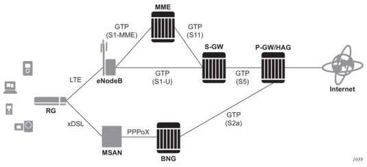
For more details on GTP uplinks, see the GTP section in this guide.