3. Virtual Private LAN Service
3.1. VPLS Service Overview
VPLS as described in RFC 4905, Encapsulation methods for transport of layer 2 frames over MPLS, is a class of virtual private network service that allows the connection of multiple sites in a single bridged domain over a provider-managed IP/MPLS network. The customer sites in a VPLS instance appear to be on the same LAN, regardless of their location. VPLS uses an Ethernet interface on the customer-facing (access) side, which simplifies the LAN/WAN boundary and allows for rapid and flexible service provisioning.
VPLS offers a balance between point-to-point Frame Relay service and outsourced routed services (VPRN). VPLS enables each customer to maintain control of their own routing strategies. All customer routers in the VPLS service are part of the same subnet (LAN), which simplifies the IP addressing plan, especially when compared to a mesh constructed from many separate point-to-point connections. The VPLS service management is simplified since the service is not aware of nor participates in the IP addressing and routing.
A VPLS service provides connectivity between two or more SAPs on one (which is considered a local service) or more (which is considered a distributed service) service routers. The connection appears to be a bridged domain to the customer sites so protocols, including routing protocols, can traverse the VPLS service.
Other VPLS advantages include:
- VPLS is a transparent, protocol-independent service.
- There is no Layer 2 protocol conversion between LAN and WAN technologies.
- There is no need to design, manage, configure, and maintain separate WAN access equipment, which eliminates the need to train personnel on WAN technologies such as Frame Relay.
3.1.1. VPLS Packet Walkthrough
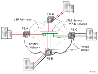
This section provides an example of VPLS processing of a customer packet sent across the network from site A, which is connected to PE Router A, to site B, which is connected to PE Router C (see Figure 56).
Figure 56: VPLS Service Architecture
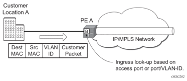
- PE Router A (Figure 57)
- Service packets arriving at PE Router A are associated with a VPLS service instance based on the combination of the physical port and the IEEE 802.1Q tag (VLAN ID) in the packet.
Figure 57: Access Port Ingress Packet Format and Lookup
- PE Router A learns the source MAC address in the packet and creates an entry in the FDB table that associates the MAC address with the service access point (SAP) on which it was received.
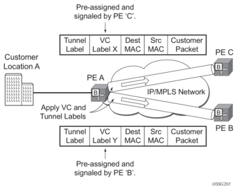
- The destination MAC address in the packet is looked up in the FDB table for the VPLS instance. There are two possibilities: either the destination MAC address has already been learned (known MAC address) or the destination MAC address is not yet learned (unknown MAC address).For a Known MAC Address (Figure 58)
- If the destination MAC address has already been learned by PE Router A, an existing entry in the FDB table identifies the far-end PE router and the service VC-label (inner label) to be used before sending the packet to far-end PE Router C.
- PE Router A chooses a transport LSP to send the customer packets to PE Router C. The customer packet is sent on this LSP after the IEEE 802.1Q tag is stripped and the service VC-label (inner label) and the transport label (outer label) are added to the packet.For an Unknown MAC Address (Figure 58)If the destination MAC address has not been learned, PE Router A will flood the packet to both PE Router B and PE Router C that are participating in the service by using the VC-labels that each PE Router previously added for the VPLS instance. The packet is not sent to PE Router D because this VPLS service does not exist on that PE router.
Figure 58: Network Port Egress Packet Format and Flooding
- Core Router SwitchingAll the core routers (“P” routers in IETF nomenclature) between PE Router A and PE Router B and PE Router C are Label Switch Routers (LSRs) that switch the packet based on the transport (outer) label of the packet until the packet arrives at the far-end PE Router. All core routers are unaware that this traffic is associated with a VPLS service.
- PE Router C
- PE Router C strips the transport label of the received packet to reveal the inner VC-label. The VC-label identifies the VPLS service instance to which the packet belongs.
- PE Router C learns the source MAC address in the packet and creates an entry in the FDB table that associates the MAC address with PE Router A, and the VC-label that PE Router A added for the VPLS service on which the packet was received.
- The destination MAC address in the packet is looked up in the FDB table for the VPLS instance. Again, there are two possibilities: either the destination MAC address has already been learned (known MAC address) or the destination MAC address has not been learned on the access side of PE Router C (unknown MAC address).For a Known MAC Address (Figure 59)
If the destination MAC address has been learned by PE Router C, an existing entry in the FDB table identifies the local access port and the IEEE 802.1Q tag to be added before sending the packet to customer Location C. The egress Q tag may be different than the ingress Q tag.
Figure 59: Access Port Egress Packet Format and Lookup

3.2. VPLS Features
This section provides information about VPLS features.
3.2.1. VPLS Enhancements
Nokia’s VPLS implementation includes several enhancements beyond basic VPN connectivity. The following VPLS features can be configured individually for each VPLS service instance:
- Extensive MAC and IP filter support (up to Layer 4). Filters can be applied on a per-SAP basis.
- Forwarding Database (FDB) management features on a per service-level basis including:
- Configurable FDB size limit. On the 7450 ESS, it can be configured on a per-VPLS, per-SAP, and per spoke-SDP basis.
- FDB size alarms. On the 7450 ESS, it can be configured on a per-VPLS basis.
- MAC learning disable. On the 7450 ESS, it can be configured on a per-VPLS, per-SAP, and per spoke-SDP basis.
- Discard unknown. On the 7450 ESS, it can be configured on a per-VPLS basis.
- Separate aging timers for locally and remotely learned MAC addresses.
- Ingress rate limiting for broadcast, multicast, and unknown destination flooding on a per-SAP basis.
- Implementation of STP parameters on a per-VPLS, per-SAP, and per spoke-SDP basis.
- A split horizon group on a per-SAP and per spoke-SDP basis.
- DHCP snooping and anti-spoofing on a per-SAP and per-SDP basis for the 7450 ESS or 7750 SR.
- IGMP snooping on a per-SAP and per-SDP basis.
- Optional SAP and/or spoke-SDP redundancy to protect against node failure.
3.2.2. VPLS over MPLS
The VPLS architecture proposed in RFC 4762, Virtual Private LAN Services Using LDP Signaling specifies the use of provider equipment (PE) that is capable of learning, bridging, and replication on a per-VPLS basis. The PE routers that participate in the service are connected using MPLS Label Switched Path (LSP) tunnels in a full-mesh composed of mesh SDPs or based on an LSP hierarchy (Hierarchical VPLS (H-VPLS)) composed of mesh SDPs and spoke-SDPs.
Multiple VPLS services can be offered over the same set of LSP tunnels. Signaling specified in RFC 4905, Encapsulation methods for transport of layer 2 frames over MPLS is used to negotiate a set of ingress and egress VC labels on a per-service basis. The VC labels are used by the PE routers for demultiplexing traffic arriving from different VPLS services over the same set of LSP tunnels.
VPLS is provided over MPLS by:
- connecting bridging-capable provider edge routers with a full mesh of MPLS LSP tunnels
- negotiating per-service VC labels using draft-Martini encapsulation
- replicating unknown and broadcast traffic in a service domain
- enabling MAC learning over tunnel and access ports (see VPLS MAC Learning and Packet Forwarding)
- using a separate FDB per VPLS service
3.2.3. VPLS Service Pseudowire VLAN Tag Processing
VPLS services can be connected using pseudowires that can be provisioned statically or dynamically and are represented in the system as either a mesh or a spoke-SDP. The mesh and spoke-SDP can be configured to process zero, one, or two VLAN tags as traffic is transmitted and received. In the transmit direction, VLAN tags are added to the frame being sent, and in the received direction, VLAN tags are removed from the frame being received. This is analogous to the SAP operations on a null, dot1q, and QinQ SAP.
The system expects a symmetrical configuration with its peer; specifically, it expects to remove the same number of VLAN tags from received traffic as it adds to transmitted traffic. When removing VLAN tags from a mesh or spoke-SDP, the system attempts to remove the configured number of VLAN tags (see the following configuration information); if fewer tags are found, the system removes the VLAN tags found and forwards the resulting packet. As some of the related configuration parameters are local and not communicated in the signaling plane, an asymmetrical behavior cannot always be detected and so cannot be blocked. With an asymmetrical behavior, protocol extractions will not necessarily function as they would with a symmetrical configuration, resulting in an unexpected operation.
The VLAN tag processing is configured as follows on a mesh or spoke-SDP in a VPLS service:
- Zero VLAN tags processed — VPLS Service Pseudowire VLAN Tag Processing. This requires the configuration of vc-type ether under the mesh-SDP or spoke-SDP, or in the related PW template.
- One VLAN tag processed — This requires one of the following configurations:
- vc-type vlan under the mesh-SDP or spoke-SDP, or in the related PW template
- vc-type ether and force-vlan-vc-forwarding under the mesh-SDP or spoke-SDP, or in the related PW template
- Two VLAN tags processed—This requires the configuration of force-qinq-vc-forwarding [c-tag-c-tag | s-tag-c-tag] under the mesh-SDP or spoke-SDP, or in the related PW template.
The PW template configuration provides support for BGP VPLS services and LDP VPLS services using BGP Auto-Discovery.
The following restrictions apply to VLAN tag processing:
- The configuration of vc-type vlan and force-vlan-vc-forwarding is mutually exclusive.
- BGP VPLS services operate in a mode equivalent to vc-type ether; consequently, the configuration of vc-type vlan in a PW template for a BGP VPLS service is ignored.
- force-qinq-vc-forwarding [c-tag-c-tag | s-tag-c-tag] can be configured with the mesh-SDP or spoke-SDP signaled as either vc-type ether or vc-type vlan.
- The following are not supported with force-qinq-vc-forwarding [c-tag-c-tag | s-tag-c-tag] configured under the mesh-SDP or spoke-SDP, or in the related PW template:
- Routed, E-Tree, or PBB VPLS services (including B-VPLS and I-VPLS)
- L2PT termination on QinQ mesh-SDP or spoke-SDPs
- IGMP/MLD/PIM snooping within the VPLS service
- force-vlan-vc-forwarding under the same spoke-SDP or PW template
- Eth-CFM LM tests
Table 31 and Table 32 describe the VLAN tag processing with respect to the zero, one, and two VLAN tag configuration described for the VLAN identifiers, Ethertype, ingress QoS classification (dot1p/DE), and QoS propagation to the egress (which can be used for egress classification and/or to set the QoS information in the innermost egress VLAN tag).
Table 31: VPLS Mesh and Spoke-SDP VLAN Tag Processing: Ingress
Ingress (received on mesh or spoke-SDP) | Zero VLAN tags | One VLAN tag | Two VLAN Tags (enabled by force-qinq-vc-forwarding [c-tag-c-tag | s-tag-c-tag] |
VLAN identifiers | N/A | Ignored | Both inner and outer ignored |
Ethertype (to determine the presence of a VLAN tag) | N/A | 0x8100 or value configured under sdp vlan-vc-etype | Both inner and outer VLAN tags: 0x8100, or outer VLAN tag value configured under sdp vlan-vc-etype (inner VLAN tag value must be 0x8100) |
Ingress QoS (dot1p/DE) classification | N/A | Ignored | Both inner and outer ignored |
QoS (dot1p/DE) propagation to egress | Dot1p/DE=0 | Dot1p/DE taken from received VLAN tag | Dot1p/DE taken as follows:
|
Table 32: VPLS Mesh and Spoke-SDP VLAN Tag Processing: Egress
Egress (sent on mesh or spoke-SDP) | Zero VLAN tags | One VLAN tag | Two VLAN Tags (enabled by force-qinq-vc-forwarding [c-tag-c-tag | s-tag-c-tag] |
VLAN identifiers (set in VLAN tags) | N/A | For one VLAN tag, one of the following applies:
| The inner and outer VLAN tags are derived from one of the following:
|
| |||
Ethertype (set in VLAN tags) | N/A | 0x8100 or value configured under sdp vlan-vc-etype | Both inner and outer VLAN tags: 0x8100, or outer VLAN tag value configured under sdp vlan-vc-etype (inner VLAN tag value will be 0x8100) |
Egress QoS (dot1p/DE) (set in VLAN tags) | N/A | Taken from the innermost ingress service delimiting tag, one of the following applies:
| Inner and outer dot1p/DE: If c-tag-c-tag is configured, the inner and outer dot1p/DE bits are both taken from the innermost ingress service delimiting tag. It can be one of the following:
|
Egress QoS (dot1p/DE) (set in VLAN tags) | N/A |
Note: Neither the inner nor outer dot1p/DE values can be explicitly set. |
If s-tag-c-tag is configured, the inner and outer dot1p/DE bits are taken from the inner and outer ingress service delimiting tag (respectively). They can be:
|
Any non-service delimiting VLAN tags are forwarded transparently through the VPLS service. SAP egress classification is possible on the outermost customer VLAN tag received on a mesh or spoke-SDP using the ethernet-ctag parameter in the associated SAP egress QoS policy.
3.2.4. VPLS MAC Learning and Packet Forwarding
The 7950 XRS, 7750 SR, and 7450 ESS perform the packet replication required for broadcast and multicast traffic across the bridged domain. MAC address learning is performed by the router to reduce the amount of unknown destination MAC address flooding.
The 7450 ESS, 7750 SR, and 7950 XRS routers learn the source MAC addresses of the traffic arriving on their access and network ports.
Each router maintains an FDB for each VPLS service instance and learned MAC addresses are populated in the FDB table of the service. All traffic is switched based on MAC addresses and forwarded between all objects in the VPLS service. Unknown destination packets (for example, the destination MAC address has not been learned) are forwarded on all objects to all participating nodes for that service until the target station responds and the MAC address is learned by the routers associated with that service.
3.2.4.1. MAC Learning Protection
In a Layer 2 environment, subscribers or customers connected to SAPs A or B can create a denial of service attack by sending packets sourcing the gateway MAC address. This will move the learned gateway MAC from the uplink SDP/SAP to the subscriber’s or customer’s SAP causing all communication to the gateway to be disrupted. If local content is attached to the same VPLS (D), a similar attack can be launched against it. Communication between subscribers or customers is also disallowed but split horizon will not be sufficient in the topology shown in Figure 60.
Figure 60: MAC Learning Protection
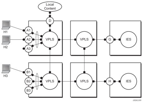
The 7450 ESS, 7750 SR, and 7950 XRS routers enable MAC learning protection capability for SAPs and SDPs. With this mechanism, forwarding and learning rules apply to the non-protected SAPs. Assume hosts H1, H2, and H3 (Figure 60) are non-protected while IES interfaces G and H are protected. When a frame arrives at a protected SAP/SDP, the MAC is learned as usual. When a frame arrives from a non-protected SAP or SDP, the frame must be dropped if the source MAC address is protected and the MAC address is not relearned. The system allows only packets with a protected MAC destination address.
The system can be configured statically. The addresses of all protected MACs are configured. Only the IP address can be included and use a dynamic mechanism to resolve the MAC address (cpe-ping). All protected MACs in all VPLS instances in the network must be configured.
To eliminate the ability of a subscriber or customer to cause a DoS attack, the node restricts the learning of protected MAC addresses based on a statically defined list. Also, the destination MAC address is checked against the protected MAC list to verify that a packet entering a restricted SAP has a protected MAC as a destination.
3.2.4.2. DEI in IEEE 802.1ad
The IEEE 802.1ad-2005 standard allows drop eligibility to be conveyed separately from priority in Service VLAN TAGs (S-TAGs) so that all of the previously introduced traffic types can be marked as drop eligible. The S-TAG has a new format where the priority and discard eligibility parameters are conveyed in the 3-bit Priority Code Point (PCP) field and, respectively, in the DE bit (Figure 61).
Figure 61: DE Bit in the 802.1ad S-TAG
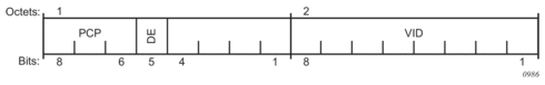
The DE bit allows the S-TAG to convey eight forwarding classes/distinct emission priorities, each with a drop eligible indication.
When the DE bit is set to 0 (DE=FALSE), the related packet is not discard eligible. This is the case for the packets that are within the CIR limits and must be given priority in case of congestion. If the DEI is not used or backwards compliance is required, the DE bit should be set to zero on transmission and ignored on reception.
When the DE bit is set to 1 (DE=TRUE), the related packet is discard eligible. This is the case for the packets that are sent above the CIR limit (but below the PIR). In case of congestion, these packets will be the first ones to be dropped.
3.2.5. VPLS Using G.8031 Protected Ethernet Tunnels
The use of MPLS tunnels provides a way to scale the core while offering fast failover times using MPLS FRR. In environments where Ethernet services are deployed using native Ethernet backbones, Ethernet tunnels are provided to achieve the same fast failover times as in the MPLS FRR case. There are still service provider environments where Ethernet services are deployed using native Ethernet backbones.
The Nokia VPLS implementation offers the capability to use core Ethernet tunnels compliant with ITU-T G.8031 specification to achieve 50 ms resiliency for backbone failures. This is required to comply with the stringent SLAs provided by service providers in the current competitive environment. The implementation also allows a LAG-emulating Ethernet tunnel providing a complimentary native Ethernet E-LAN capability. The LAG-emulating Ethernet tunnels and G.8031 protected Ethernet tunnels operate independently (refer to “LAG emulation using Ethernet Tunnels” in the Services Overview Guide).
When using Ethernet tunnels, the Ethernet tunnel logical interface is created first. The Ethernet tunnel has member ports that are the physical ports supporting the links. The Ethernet tunnel controls SAPs that carry G.8031 and 802.1ag control traffic and user data traffic. Ethernet Service SAPs are configured on the Ethernet tunnel. Optionally, when tunnels follow the same paths, end-to-end services are configured with same-fate Ethernet tunnel SAPs, which carry only user data traffic, and share the fate of the Ethernet tunnel port (if properly configured).
When configuring VPLS and B-VPLS using Ethernet tunnels, the services are very similar.
Refer to the IEEE 802.1ah PBB Guide for examples.
3.2.6. Pseudowire Control Word
The control-word command enables the use of the control word individually on each mesh SDP or spoke-SDP. By default, the control word is disabled. When the control word is enabled, all VPLS packets, including the BPDU frames, are encapsulated with the control word. The Targeted LDP (T-LDP) control plane behavior will be the same as the control word for VLL services. The configuration for the two directions of the Ethernet pseudowire should match.
3.2.7. Table Management
The following sections describe VPLS features related to management of the FDB.
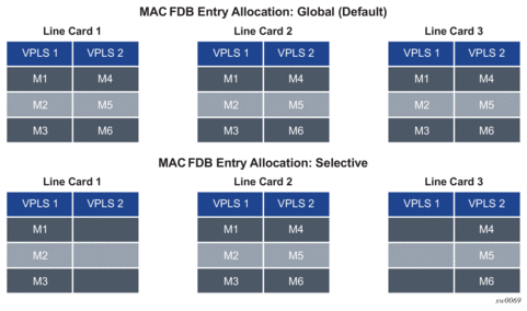
3.2.7.1. Selective MAC Address Learning
Source MAC addresses are learned in a VPLS service by default with an entry allocated in the FDB for each address on all line cards. Therefore, all MAC addresses are considered to be global. This operation can be modified so that the line card allocation of some MAC addresses is selective, based on where the service has a configured object.
An example of the advantage of selective MAC address learning is for services to benefit from the higher MAC address scale of some line cards (particularly for network interfaces used by mesh or spoke-SDPs, EVPN-VXLAN tunnels, and EVPN-MPLS destinations) while using lower MAC address scale cards for the SAPs.
Selective MAC addresses are those learned locally and dynamically in the data path (displayed in the show output with type “L”) or by EVPN (displayed in the show output with type “Evpn”, excluding those with the sticky bit set, which are displayed with type “EvpnS”). An exception is when a MAC address configured as a conditional static MAC address is learned dynamically on an object other than its monitored object; this can be displayed with type “L” or “Evpn” but is learned as global because of the conditional static MAC configuration.
Selective MAC addresses have FDB entries allocated on line cards where the service has a configured object. When a MAC address is learned, it is allocated an FDB entry on all line cards on which the service has a SAP configured (for LAG or Ethernet tunnel SAPs, the MAC address is allocated an FDB entry on all line cards on which that LAG or Ethernet tunnel has configured ports) and on all line cards that have a network interface port if the service is configured with VXLAN, EVPN-MPLS, or a mesh or spoke-SDP.
When using selective learning in an I-VPLS service, the learned CMACs are allocated FDB entries on all the line cards where the I-VPLS service has a configured object and on the line cards on which the associated B-VPLS has a configured object. When using selective learning in a VPLS service with allow-ip-intf-bind configured (for it to become an R-VPLS), FDB entries are allocated on all line cards on which there is an IES or VPRN interface.
If a new configured object is added to a service and there are sufficient MAC FDB resources available on the new line cards, the selective MAC addresses present in the service are allocated on the new line cards. Otherwise, if any of the selective MAC addresses currently learned in the service cannot be allocated an FDB entry on the new line cards, those MAC addresses will be deleted from all line cards. Such a deletion increments the FailedMacCmplxMapUpdts statistic displayed in the tools dump service vpls-fdb-stats output.
When the set of configured objects changes for a service using selective learning, the system must reallocate its FDB entries accordingly, which can cause FDB entry "allocate" or "free" operations to become pending temporarily. The pending operations can be displayed using the tools dump service id fdb command.
When a global MAC address is to be learned, there must be a free FDB entry in the service and system FDBs and on all line cards in the system for it to be accepted. When a selective MAC address is to be learned, there must be a free FDB entry in the service and system FDBs and on all line cards where the service has a configured object for it to be accepted.
To demonstrate the selective MAC address learning logic, consider the following:
- a system has three line cards: 1, 2, and 3
- two VPLS services are configured on the system:
- VPLS 1 having learned MAC addresses M1, M2, and M3 and has configured SAPs 1/1/1 and 2/1/1
- VPLS 2 having learned MAC addresses M4, M5, and M6 and has configured SAPs 2/1/2 and 3/1/1
This is shown in Table 33.
Table 33: MAC Address Learning Logic Example
Learned MAC addresses | Configured SAPs | |
VPLS1 | M1, M2, M3 | SAP 1/1/1 SAP 2/1/1 |
VPLS2 | M4, M5, M6 | SAP 2/1/2 SAP 3/1/1 |
Figure 62 shows the FDB entry allocation when the MAC addresses are global and when they are selective. Notice that in the selective case, all MAC addresses are allocated FDB entries on line card 2, but line card 1 and 3 only have FDB entries allocated for services VPLS 1 and VPLS 2, respectively.
Figure 62: MAC FDB Entry Allocation: Global versus Selective
Selective MAC address learning can be enabled as follows within any VPLS service, except for B-VPLS and R-VPLS services:
Enabling selective MAC address learning has no effect on single line card systems.
When selective learning is enabled or disabled in a VPLS service, the system may need to reallocate FDB entries; this can cause temporary pending FDB entry allocate or free operations. The pending operations can be displayed using the tools dump service id fdb command.
3.2.7.1.1. Example Operational Information
The show and tools dump command output can display the global and selective MAC addresses along with the MAC address limits and the number of allocated and free MAC-address FDB entries. The show output displays the system and card FDB usage, while the tools output displays the FDB per service with respect to MAC addresses and cards.
The configuration for the following output is similar to the simple example above:
- the system has three line cards: 1, 2, and 5
- the system has two VPLS services:
- VPLS 1 is an EVPN-MPLS service with a SAP on 5/1/1:1 and uses a network interface on 5/1/5.
- VPLS 2 has two SAPs on 2/1/1:2 and 2/1/2:2.
The first output shows the default where all MAC addresses are global. The second enables selective learning in the two VPLS services.
3.2.7.1.1.1. Global MAC address learning only (default)
By default, VPLS 1 and 2 are not configured for selective learning, so all MAC addresses are global:
Traffic is sent into the services, resulting in the following MAC addresses being learned:
A total of eight MAC addresses are learned. There are two MAC addresses learned locally on SAP 5/1/1:1 in service VPLS 1 (type “L”), and another two MAC addresses learned using EVPN with the sticky bit set, also in service VPLS 1 (type “EvpnS”). A further two sets of two MAC addresses are learned on SAP 2/1/1:2 and 2/1/2:2 in service VPLS 2 (type “L”).
The system and line card FDB usage is shown as follows:
The system MAC address limit is 511999, of which eight are allocated, and the rest are free. All eight MAC addresses are global and are allocated on cards 1, 2, and 5. There are no selective MAC addresses. This output can be reduced to specific line cards by specifying the card’s slot ID as a parameter to the command.
To see the MAC address information per service, tools dump commands can be used, as follows for VPLS 1. The following output displays the card status:
All of the line cards have four FDB entries allocated in VPLS 1. The “PendAlloc” and “PendFree” columns show the number of pending MAC address allocate and free operations, which are all zero.
The following output displays the MAC address status for VPLS 1:
The type and card list for each MAC address in VPLS 1 is displayed. VPLS 1 has learned four MAC addresses: the two local MAC addresses on SAP 5/1/1:1 and the two EvpnS MAC addresses. Each MAC address has an FDB entry allocated on all line cards. This output can be further reduced by optionally including a specified MAC address, a specific card, and the operational pending state.
3.2.7.1.1.2. Selective and global MAC address learning
Selective MAC address learning is now enabled in VPLS 1 and VPLS 2, as follows:
The MAC addresses learned are the same, with the same traffic being sent; however, there are now selective MAC addresses that are allocated FDB entries on different line cards.
The system and line card FDB usage is as follows:
The system MAC address limit and allocated numbers have not changed but now there are only two global MAC addresses; these are the two EvpnS MAC addresses.
There are two FDB entries allocated on card 1, which are the global MAC addresses; there are no services or network interfaces configured on card 1, so the FDB entries allocated are for the global MAC addresses.
Card 2 has six FDB entries allocated in total: two for the global MAC addresses plus four for the selective MAC addresses in VPLS 2 (these are the two sets of two local MAC addresses in VPLS 2 on SAP 2/1/1:2 and 2/1/2:2).
Card 5 has four FDB entries allocated in total: two for the global MAC addresses plus two for the selective MAC addresses in VPLS 1 (these are the two local MAC addresses in VPLS 1 on SAP 5/1/1:1).
This output can be reduced to specific line cards by specifying the card’s slot ID as a parameter to the command.
To see the MAC address information per service, tools dump commands can be used for VPLS 1.
The following output displays the card status:
There are two FDB entries allocated on line card 1, two on line card 2, and four on line card 5. The “PendAlloc” and “PendFree” columns are all zeros.
The following output displays the MAC address status for VPLS 1:
The type and card list for each MAC address in VPLS 1 is displayed. VPLS 1 has learned four MAC addresses: the two local MAC addresses on SAP 5/1/1:1 and the two EvpnS MAC addresses. The local MAC addresses are selective and have FDB entries allocated only on card 5. The global MAC addresses are allocated on all line cards. This output can be further reduced by optionally including a specified MAC address, a specific card, and the operational pending state.
3.2.7.2. System FDB Size
The system FDB table size is configurable as follows:
where table-size can have values in the range from 255999 to 2047999 (2000k).
The default, minimum, and maximum values for the table size are dependent on the chassis type. To support more than 500k MAC addresses, the CPMs provisioned in the system must have at least 16 GB memory. The maximum system FDB table size also limits the maximum FDB table size of any card within the system.
The actual achievable maximum number of MAC addresses depends on the MAC address scale supported by the active cards and whether selective learning is enabled.
If an attempt is made to configure the system FDB table size such that:
- the new size is greater than or equal to the current number of allocated FDB entries, the command succeeds and the new system FDB table size is used
- the new size is less than the number of allocated FDB entries, the command fails with an error message. In this case, the user is expected to reduce the current FDB usage (for example, by deleting statically configured MAC addresses, shutting down EVPN, clearing learned MACs, and so on) to lower the number of allocated MAC addresses in the FDB so that it does not exceed the system FDB table size being configured.
The logic when attempting a rollback is similar; however, when rolling back to a configuration where the system FDB table size is smaller than the current system FDB table size, the system will flush all learned MAC addresses (by performing a shutdown then no shutdown in all VPLS services) to allow the rollback to continue.
The system FDB table size can be larger than some of the line card FDB sizes, resulting in the possibility that the current number of allocated global MAC addresses is larger than the maximum FDB size supported on some line cards. When a new line card is provisioned, the system checks whether the line card's FDB can accommodate all of the currently allocated global MAC addresses. If it can, then the provisioning succeeds; if it cannot, then the provisioning fails and an error is reported. If the provisioning fails, the number of global MACs allocated must be reduced in the system to a number that the new line card can accommodate, then the card-type must be reprovisioned.
3.2.7.3. Per-VPLS Service FDB Size
The following MAC table management features are available for each instance of a SAP or spoke-SDP within a particular VPLS service instance:
- MAC FDB size limits — Allows users to specify the maximum number of MAC FDB entries that are learned locally for a SAP or remotely for a spoke-SDP. If the configured limit is reached, no new addresses will be learned from the SAP or spoke-SDP until at least one FDB entry is aged out or cleared.
- When the limit is reached on a SAP or spoke-SDP, packets with unknown source MAC addresses are still forwarded (this default behavior can be changed by configuration). By default, if the destination MAC address is known, it is forwarded based on the FDB, and if the destination MAC address is unknown, it will be flooded. Alternatively, if discard unknown is enabled at the VPLS service level, any packets from unknown source MAC addresses are discarded at the SAP.
- The log event SAP MAC Limit Reached is generated when the limit is reached. When the condition is cleared, the log event SAP MAC Limit Reached Condition Cleared is generated.
- Disable learning allows users to disable the dynamic learning function on a SAP or a spoke-SDP of a VPLS service instance.
- Disable aging allows users to turn off aging for learned MAC addresses on a SAP or a spoke-SDP of a VPLS service instance.
3.2.7.4. System FDB Size Alarms
High and low watermark alarms give warning when the system MAC FDB usage is high. An alarm is generated when the number of FDB entries allocated in the system FDB reaches 95% of the total system FDB table size and is cleared when it reduces to 90% of the system FDB table size. These percentages are not configurable.
3.2.7.5. Line Card FDB Size Alarms
High and low watermark alarms give warning when a line card's MAC FDB usage is high. An alarm is generated when the number of FDB entries allocated in a line card FDB reaches 95% of its maximum FDB table size and is cleared when it reduces to 90% of its maximum FDB table size. These percentages are not configurable.
3.2.7.6. Per VPLS FDB Size Alarms
The size of the VPLS FDB can be configured with a low watermark and a high watermark, expressed as a percentage of the total FDB size limit. If the actual FDB size grows above the configured high watermark percentage, an alarm is generated. If the FDB size falls below the configured low watermark percentage, the alarm is cleared by the system.
3.2.7.7. Local and Remote Aging Timers
Like a Layer 2 switch, learned MACs within a VPLS instance can be aged out if no packets are sourced from the MAC address for a specified period of time (the aging time). In each VPLS service instance, there are independent aging timers for locally learned MAC and remotely learned MAC entries in the FDB. A local MAC address is a MAC address associated with a SAP because it ingressed on a SAP. A remote MAC address is a MAC address received by an SDP from another router for the VPLS instance. The local-age timer for the VPLS instance specifies the aging time for locally learned MAC addresses, and the remote-age timer specifies the aging time for remotely learned MAC addresses.
In general, the remote-age timer is set to a longer period than the local-age timer to reduce the amount of flooding required for unknown destination MAC addresses. The aging mechanism is considered a low priority process. In most situations, the aging out of MAC addresses happens within tens of seconds beyond the age time. However, it, can take up to two times their respective age timer to be aged out.
3.2.7.8. Disable MAC Aging
The MAC aging timers can be disabled, which will prevent any learned MAC entries from being aged out of the FDB. When aging is disabled, it is still possible to manually delete or flush learned MAC entries. Aging can be disabled for learned MAC addresses on a SAP or a spoke-SDP of a VPLS service instance.
3.2.7.9. Disable MAC Learning
When MAC learning is disabled for a service, new source MAC addresses are not entered in the VPLS FDB, whether the MAC address is local or remote. MAC learning can be disabled for individual SAPs or spoke-SDPs.
3.2.7.10. Unknown MAC Discard
Unknown MAC discard is a feature that discards all packets ingressing the service where the destination MAC address is not in the FDB. The normal behavior is to flood these packets to all endpoints in the service.
Unknown MAC discard can be used with the disable MAC learning and disable MAC aging options to create a fixed set of MAC addresses allowed to ingress and traverse the service.
3.2.7.11. VPLS and Rate Limiting
Traffic that is normally flooded throughout the VPLS can be rate limited on SAP ingress through the use of service ingress QoS policies. In a service ingress QoS policy, individual queues can be defined per forwarding class to provide shaping of broadcast traffic, MAC multicast traffic, and unknown destination MAC traffic.
3.2.7.12. MAC Move
The MAC move feature is useful to protect against undetected loops in a VPLS topology as well as the presence of duplicate MACs in a VPLS service.
If two clients in the VPLS have the same MAC address, the VPLS will experience a high relearn rate for the MAC. When MAC move is enabled, the 7450 ESS, 7750 SR, or 7950 XRS will shut down the SAP or spoke-SDP and create an alarm event when the threshold is exceeded.
MAC move allows sequential order port blocking. By configuration, some VPLS ports can be configured as “non-blockable”, which allows a simple level of control of which ports are being blocked during loop occurrence. There are two sophisticated control mechanisms that allow blocking of ports in a sequential order:
- Configuration capabilities to group VPLS ports and to define the order in which they should be blocked
- Criteria defining when individual groups should be blocked
For the first control mechanism, configuration CLI is extended by definition of “primary” and “secondary” ports. Per default, all VPLS ports are considered “tertiary” ports unless they are explicitly declared primary or secondary. The order of blocking will always follow a strict order starting from tertiary to secondary, and then primary.
The definition of criteria for the second control mechanism is the number of periods during which the specified relearn rate has been exceeded. The mechanism is based on the cumulative factor for every group of ports. Tertiary VPLS ports are blocked if the relearn rate exceeds the configured threshold during one period, while secondary ports are blocked only when relearn rates are exceeded during two consecutive periods, and primary ports when exceeded during three consecutive periods. The retry timeout period must be larger than the period before blocking the highest priority port so that the retry timeout sufficiently spans across the period required to block all ports in sequence. The period before blocking the highest priority port is the cumulative factor of the highest configured port multiplied by 5 seconds (the retry timeout can be configured through the CLI).
3.2.7.13. Auto-Learn MAC Protect
This section provides information about auto-learn-mac-protect and restrict-protected-src discard-frame features.
VPLS solutions usually involve learning MAC addresses in order for traffic to be forwarded to the correct SAP/SDP. If a MAC address is learned on the wrong SAP/SDP, traffic would be redirected away from its intended destination. This could occur through a misconfiguration, a problem in the network, or by a malicious source creating a DoS attack, and is applicable to any type of VPLS network; for example, mobile backhaul or residential service delivery networks. The auto-learn-mac-protect feature can be used to safeguard against the possibility of MAC addresses being learned on the wrong SAP/SDP.
This feature provides the ability to automatically protect source MAC addresses that have been learned on a SAP or a spoke/mesh SDP and prevent frames with the same protected source MAC address from entering into a different SAP/spoke or mesh SDP.
This is a complementary solution to features such as mac-move and mac-pinning, but has the advantage that MAC moves are not seen and it has a low operational complexity. If a MAC is initially learned on the wrong SAP/SDP, the operator can clear the MAC from the MAC FDB in order for it to be relearned on the correct SAP/SDP.
Two separate commands are used, which provide the configuration flexibility of separating the identification (learning) function from the application of the restriction (discard).
The auto-learn-mac-protect and restrict-protected-src commands allow the following functions:
- the ability to enable the automatic protection of a learned MAC using the auto-learn-mac-protect command under a SAP/spoke or mesh SDP/SHG context
- the ability to discard frames associated with automatically protected MACs instead of shutting down the entire SAP/SDP as with the restrict-protected-src feature. This is enabled using a restrict-protected-src discard-frame command in the SAP/spoke or mesh SDP/SHG context. An optimized alarm mechanism is used to generate alarms related to these discards. The frequency of alarm generation is fixed to be, at most, one alarm per MAC address per forwarding complex per 10 minutes in a VPLS service.
If the auto-learn-mac-protect or restrict-protected-src discard-frame feature is configured under an SHG, the operation applies only to SAPs in the SHG, not to spoke-SDPs in the SHG. If required, these parameters can also be enabled explicitly under specific SAPs/spoke-SDPs within the SHG.
Applying or removing auto-learn-mac-protect or restrict-protected-src discard-frame to/from a SAP, spoke or mesh SDP, or SHG, will clear the MACs on the related objects (for the SHG, this results in clearing the MACs only on the SAPs within the SHG).
The use of restrict-protected-src discard-frame is mutually exclusive with both the restrict-protected-src [alarm-only] command and with the configuration of manually protected MAC addresses, using the mac-protect command, within a specified VPLS.
The following rules govern the changes to the state of protected MACs:
- Automatically learned protected MACs are subject to normal removal, aging (unless disabled), and flushing, at which time the associated entries are removed from the FDB.
- Automatically learned protected MACs can only move from their learned SAP/spoke or mesh SDP if they enter a SAP/spoke or mesh SDP without restrict-protected-src enabled.
If a MAC address does legitimately move between SAPs/spoke or mesh SDPs after it has been automatically protected on a specified SAP/spoke or mesh SDP (thereby causing discards when received on the new SAP/spoke or mesh SDP), the operator must manually clear the MAC from the FDB for it to be learned in the new/correct location.
MAC addresses that are manually created (using static-mac, static-host with a MAC address specified, or oam mac-populate) will not be protected even if they are configured on a SAP/spoke or mesh SDP that has auto-learn-mac-protect enabled on it. Also, the MAC address associated with an R-VPLS IP interface is protected within its VPLS service such that frames received with this MAC address as the source address are discarded (this is not based on the auto-learn MAC protect function). However, VRRP MAC addresses associated with an R-VPLS IP interface are not protected either in this way or using the auto-learn MAC protect function.
MAC addresses that are dynamically created (learned, using static-host with no MAC address specified, or lease-populate) will be protected when the MAC address is learned on a SAP/spoke or mesh SDP that has auto-learn-mac-protect enabled on it.
The actions of the following features are performed in the order listed.
- Restrict-protected-src
- MAC-pinning
- MAC-move
3.2.7.13.1. Operation
Figure 63 shows a specific configuration using auto-learn-mac-protect and restrict-protected-src discard-frame in order to describe their operation for the 7750 SR, 7450 ESS, or 7950 XRS.
Figure 63: Auto-Learn-Mac-Protect Operation
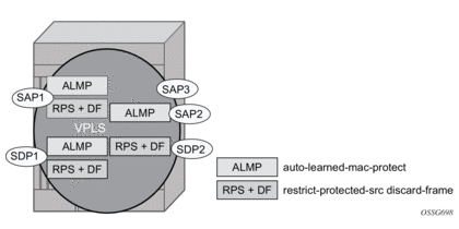
A VPLS service is configured with SAP1 and SDP1 connecting to access devices and SAP2, SAP3, and SDP2 connecting to the core of the network. The auto-learn-mac-protect feature is enabled on SAP1, SAP3, and SDP1, and restrict-protected-src discard-frame is enabled on SAP1, SDP1, and SDP2. The following series of events describes the details of the functionality:
Assume that the FDB is empty at the start of each sequence.
Sequence 1:
- A frame with source MAC A enters SAP1, MAC A is learned on SAP1, and MAC-A/SAP1 is protected because of the presence of the auto-learn-mac-protect on SAP1.
- All subsequent frames with source MAC A entering SAP1 are forwarded into the VPLS.
- Frames with source MAC A enter either SDP1 or SDP2, these frames are discarded, and an alarm indicating MAC A and SDP1/SDP2 is initiated because of the presence of the restrict-protected-src discard-frame on SDP1/SDP2.
- The above continues, with MAC-A/SAP1 protected in the FDB until MAC A on SAP1 is removed from the FDB.
Sequence 2:
- A frame with source MAC A enters SAP1, MAC A is learned on SAP1, and MAC-A/SAP1 is protected because of the presence of the auto-learn-mac-protect on SAP1.
- A frame with source MAC A enters SAP2. As restrict-protected-src is not enabled on SAP2, MAC A is relearned on SAP2 (but not protected), replacing the MAC-A/SAP1 entry in the FDB.
- All subsequent frames with source MAC A entering SAP2 are forwarded into the VPLS. This is because restrict-protected-src is not enabled SAP2 and auto-learn-mac-protect is not enabled on SAP2, so the FDB is not changed.
- A frame with source MAC A enters SAP1, MAC A is relearned on SAP1, and MAC-A/SAP1 is protected because of the presence of the auto-learn-mac-protect on SAP1.
Sequence 3:
- A frame with source MAC A enters SDP2, MAC A is learned on SDP2, but is not protected as auto-learn-mac-protect is not enabled on SDP2.
- A frame with source MAC A enters SDP1, and MAC A is relearned on SDP1 because previously it was not protected. Consequently, MAC-A/SDP1 is protected because of the presence of the auto-learn-mac-protect on SDP1.
Sequence 4:
- A frame with source MAC A enters SAP1, MAC A is learned on SAP1, and MAC-A/SAP1 is protected because of the presence of the auto-learn-mac-protect on SAP1.
- A frame with source MAC A enters SAP3. As restrict-protected-src is not enabled on SAP3, MAC A is relearned on SAP3 and the MAC-A/SAP1 entry is removed from the FDB with MAC-A/SAP3 being added as protected to the FDB (because auto-learn-mac-protect is enabled on SAP3).
- All subsequent frames with source MAC A entering SAP3 are forwarded into the VPLS.
- A frame with source MAC A enters SAP1, these frames are discarded, and an alarm indicating MAC A and SAP1 is initiated because of the presence of the restrict-protected-src discard-frame on SAP1.
Example Use
Figure 64 shows a possible configuration using auto-learn-mac-protect and restrict-protected-src discard-frame in a mobile backhaul network, with the focus on PE1 for the 7750 SR or 7950 XRS.
Figure 64: Auto-Learn-Mac-Protect Example
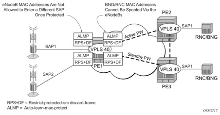
To protect the MAC addresses of the BNG/RNCs on PE1, the auto-learn-mac-protect command is enabled on the pseudowires connecting PE1 to PE2 and PE3. Enabling the restrict-protected-src discard-frame command on the SAPs toward the eNodeBs will prevent frames with the source MAC addresses of the BNG/RNCs from entering PE1 from the eNodeBs.
The MAC addresses of the eNodeBs are protected in two ways. In addition to the above commands, enabling the auto-learn-mac-protect command on the SAPs toward the eNodeBs will prevent the MAC addresses of the eNodeBs being learned on the wrong eNodeB SAP. Enabling the restrict-protected-src discard-frame command on the pseudowires connecting PE1 to PE2 and PE3 will protect the eNodeB MAC addresses from being learned on the pseudowires. This may happen if their MAC addresses are incorrectly injected into VPLS 40 on PE2/PE3 from another eNodeB aggregation PE.
The above configuration is equally applicable to other Layer 2 VPLS-based aggregation networks; for example, to business or residential service networks.
3.2.8. Split Horizon SAP Groups and Split Horizon Spoke SDP Groups
Within the context of VPLS services, a loop-free topology within a fully meshed VPLS core is achieved by applying a split horizon forwarding concept that packets received from a mesh SDP are never forwarded to other mesh SDPs within the same service. The advantage of this approach is that no protocol is required to detect loops within the VPLS core network.
In applications such as DSL aggregation, it is useful to extend this split horizon concept also to groups of SAPs and/or spoke-SDPs. This extension is referred to as a split horizon SAP group or residential bridging.
Traffic arriving on a SAP or a spoke-SDP within a split horizon group will not be copied to other SAPs and spoke-SDPs in the same split horizon group (but will be copied to SAPs/spoke-SDPs in other split horizon groups if these exist within the same VPLS).
3.2.9. VPLS and Spanning Tree Protocol
Nokia’s VPLS service provides a bridged or switched Ethernet Layer 2 network. Equipment connected to SAPs forward Ethernet packets into the VPLS service. The 7450 ESS, 7750 SR, or 7950 XRS participating in the service learns where the customer MAC addresses reside, on ingress SAPs or ingress SDPs.
Unknown destinations, broadcasts, and multicasts are flooded to all other SAPs in the service. If SAPs are connected together, either through misconfiguration or for redundancy purposes, loops can form and flooded packets can keep flowing through the network. The Nokia implementation of the STP is designed to remove these loops from the VPLS topology. This is done by putting one or several SAPs and/or spoke-SDPs in the discarding state.
Nokia’s implementation of STP incorporates some modifications to make the operational characteristics of VPLS more effective.
The STP instance parameters allow the balancing between resiliency and speed of convergence extremes. Modifying particular parameters can affect the behavior. For information on command usage, descriptions, and CLI syntax, see Configuring a VPLS Service with CLI.
3.2.9.1. Spanning Tree Operating Modes
Per VPLS instance, a preferred STP variant can be configured. The STP variants supported are:
- rstp — Rapid Spanning Tree Protocol (RSTP) compliant with IEEE 802.1D-2004 - default mode
- dot1w — Compliant with IEEE 802.1w
- comp-dot1w — Operation as in RSTP but backwards compatible with IEEE 802.1w (this mode allows interoperability with some MTU types)
- mstp — Compliant with the Multiple Spanning Tree Protocol specified in IEEE 802.1Q-REV/D5.0-09/2005. This mode of operation is only supported in a Management VPLS (M-VPLS).
While the 7450 ESS, 7750 SR, or 7950 XRS initially use the mode configured for the VPLS, it will dynamically fall back (on a per-SAP basis) to STP (IEEE 802.1D-1998) based on the detection of a BPDU of a different format. A trap or log entry is generated for every change in spanning tree variant.
Some older 802.1w compliant RSTP implementations may have problems with some of the features added in the 802.1D-2004 standard. Interworking with these older systems is improved with the comp-dot1w mode. The differences between the RSTP mode and the comp-dot1w mode are:
- The RSTP mode implements the improved convergence over shared media feature; for example, RSTP will transition from discarding to forwarding in 4 seconds when operating over shared media. The comp-dot1w mode does not implement this 802.1D-2004 improvement and transitions conform to 802.1w in 30 seconds (both modes implement fast convergence over point-to-point links).
- In the RSTP mode, the transmitted BPDUs contain the port's designated priority vector (DPV) (conforms to 802.1D-2004). Older implementations may be confused by the DPV in a BPDU and may fail to recognize an agreement BPDU correctly. This would result in a slow transition to a forwarding state (30 seconds). For this reason, in the comp-dot1w mode, these BPDUs contain the port's port priority vector (conforms to 802.1w).
The 7450 ESS, 7750 SR, and 7950 XRS support two BDPU encapsulation formats, and can dynamically switch between the following supported formats (on a per-SAP basis):
- IEEE 802.1D STP
- Cisco PVST
3.2.9.2. Multiple Spanning Tree
The Multiple Spanning Tree Protocol (MSTP) extends the concept of IEEE 802.1w RSTP by allowing grouping and associating VLANs to Multiple Spanning Tree Instances (MSTI). Each MSTI can have its own topology, which provides architecture enabling load balancing by providing multiple forwarding paths. At the same time, the number of STP instances running in the network is significantly reduced as compared to Per VLAN STP (PVST) mode of operation. Network fault tolerance is also improved because a failure in one instance (forwarding path) does not affect other instances.
The Nokia implementation of M-VPLS is used to group different VPLS instances under a single RSTP instance. Introducing MSTP into the M-VPLS allows interoperating with traditional Layer 2 switches in an access network and provides an effective solution for dual homing of many business Layer 2 VPNs into a provider network.
3.2.9.2.1. Redundancy Access to VPLS
The GigE MAN portion of the network is implemented with traditional switches. Using MSTP running on individual switches facilitates redundancy in this part of the network. To provide dual homing of all VPLS services accessing from this part of the network, the VPLS PEs must participate in MSTP.
This can be achieved by configuring M-VPLS on VPLS-PEs (only PEs directly connected to the GigE MAN network), then assigning different managed-VLAN ranges to different MSTP instances. Typically, the M-VPLS would have SAPs with null encapsulations (to receive, send, and transmit MSTP BPDUs) and a mesh SDP to interconnect a pair of VPLS PEs.
Different access scenarios are displayed in Figure 65 as an example of network diagrams dually connected to the PBB PEs:
- Access Type A — Source devices connected by null or dot1q SAPs
- Access Type B — One QinQ switch connected by QinQ/801ad SAPs
- Access Type C — Two or more ES devices connected by QinQ/802.1ad SAPs
Figure 65: Access Resiliency
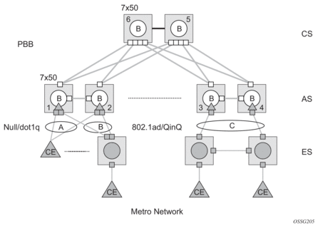
The following mechanisms are supported for the I-VPLS:
- STP/RSTP can be used for all access types.
- M-VPLS with MSTP can be used as is just for access type A. MSTP is required for access type B and C.
- LAG and MC-LAG can be used for access type A and B.
- Split-horizon-group does not require residential.
PBB I-VPLS inherits current STP configurations from the regular VPLS and M-VPLS.
3.2.9.3. MSTP for QinQ SAPs
MSTP runs in a M-VPLS context and can control SAPs from source VPLS instances. QinQ SAPs are supported. The outer tag is considered by MSTP as part of VLAN range control.
3.2.9.4. Provider MSTP
Provider MSTP is specified in IEEE-802.1ad-2005. It uses a provider bridge group address instead of a regular bridge group address used by STP, RSTP, and MSTP BPDUs. This allows for implicit separation of source and provider control planes.
The 802.1ad access network sends PBB PE P-MSTP BPDUs using the specified MAC address and also works over QinQ interfaces. P-MSTP mode is used in PBBN for core resiliency and loop avoidance.
Similar to regular MSTP, the STP mode (for example, PMSTP) is only supported in VPLS services where the m-VPLS flag is configured.
3.2.9.4.1. MSTP General Principles
MSTP represents a modification of RSTP that allows the grouping of different VLANs into multiple MSTIs. To enable different devices to participate in MSTIs, they must be consistently configured. A collection of interconnected devices that have the same MST configuration (region-name, revision, and VLAN-to-instance assignment) comprises an MST region.
There is no limit to the number of regions in the network, but every region can support a maximum of 16 MSTIs. Instance 0 is a special instance for a region, known as the Internal Spanning Tree (IST) instance. All other instances are numbered from 1 to 4094. IST is the only spanning-tree instance that sends and receives BPDUs (typically, BPDUs are untagged). All other spanning-tree instance information is included in MSTP records (M-records), which are encapsulated within MSTP BPDUs. This means that a single BPDU carries information for multiple MSTIs, which reduces overhead of the protocol.
Any MSTI is local to an MSTP region and completely independent from an MSTI in other MST regions. Two redundantly connected MST regions will use only a single path for all traffic flows (no load balancing between MST regions or between MST and SST region).
Traditional Layer 2 switches running MSTP protocol assign all VLANs to the IST instance per default. The operator may then “re-assign” individual VLANs to a specified MSTI by configuring per VLAN assignment. This means that an SR-series PE can be considered as a part of the same MST region only if the VLAN assignment to IST and MSTIs is identical to the one of Layer 2 switches in the access network.
3.2.9.4.2. MSTP in the SR-series Platform
The SR-series platform uses a concept of M-VPLS to group different SAPs under a single STP instance. The VLAN range covering SAPs to be managed by a specified M-VPLS is declared under a specific M-VPLS SAP definition. MSTP mode-of-operation is only supported in an M-VPLS.
When running MSTP, by default, all VLANs are mapped to the CIST. At the VPLS level, VLANs can be assigned to specific MSTIs. When running RSTP, the operator must explicitly indicate, per SAP, which VLANs are managed by that SAP.
3.2.9.5. Enhancements to the Spanning Tree Protocol
To interconnect PE devices across the backbone, service tunnels (SDPs) are used. These service tunnels are shared among multiple VPLS instances. The Nokia implementation of the STP incorporates some enhancements to make the operational characteristics of VPLS more effective. The implementation of STP on the router is modified in order to guarantee that service tunnels will not be blocked in any circumstance without imposing artificial restrictions on the placement of the root bridge within the network. The modifications introduced are fully compliant with the 802.1D-2004 STP specification.
When running MSTP, spoke-SDPs cannot be configured. Also, ensure that all bridges connected by mesh SDPs are in the same region. If not, the mesh will be prevented from becoming active (trap is generated).
To achieve this, all mesh SDPs are dynamically configured as either root ports or designated ports. The PE devices participating in each VPLS mesh determine (using the root path cost learned as part of the normal protocol exchange) which of the 7450 ESS, 7750 SR, or 7950 XRS devices is closest to the root of the network. This PE device is internally designated as the primary bridge for the VPLS mesh. As a result of this, all network ports on the primary bridges are assigned the designated port role and therefore remain in the forwarding state.
The second part of the solution ensures that the remaining PE devices participating in the STP instance see the SDP ports as a lower-cost path to the root rather than a path that is external to the mesh. Internal to the PE nodes participating in the mesh, the SDPs are treated as zero-cost paths toward the primary bridge. As a consequence, the path through the mesh is seen as lower cost than any alternative and the PE node will designate the network port as the root port. This approach ensures that network ports always remain in forwarding state.
In combination, these two features ensure that network ports will never be blocked and will maintain interoperability with bridges external to the mesh that are running STP instances.
3.2.9.5.1. L2PT Termination
L2PT is used to transparently transport protocol data units (PDUs) of Layer 2 protocols such as STP, CDP, VTP, PAGP, and UDLD. This allows running these protocols between customer CPEs without involving backbone infrastructure.
The 7450 ESS, 7750 SR, and 7950 XRS routers allow transparent tunneling of PDUs across the VPLS core. However, in some network designs, the VPLS PE is connected to CPEs through a legacy Layer 2 network, rather than having direct connections. In such environments, termination of tunnels through such infrastructure is required.
L2PT tunnels PDUs by overwriting MAC destination addresses at the ingress of the tunnel to a proprietary MAC address such as 01-00-0c-cd-cd-d0. At the egress of the tunnel, this MAC address is then overwritten back to the MAC address of the respective Layer 2 protocol.
The 7450 ESS, 7750 SR, and 7950 XRS routers support L2PT termination for STP BPDUs. More specifically:
- At ingress of every SAP/spoke-SDP that is configured as L2PT termination, all PDUs with a MAC destination address of 01-00-0c-cd-cd-d0 will be intercepted and their MAC destination address will be overwritten to the MAC destination address used for the corresponding protocol (PVST, STP, RSTP). The type of the STP protocol can be derived from LLC and SNAP encapsulation.
- In the egress direction, all STP PDUs received on all VPLS ports will be intercepted and L2PT encapsulation will be performed for SAP/spoke-SDPs configured as L2PT termination points. Because of implementation reasons, PDU interception and redirection to CPM can be performed only at ingress. Therefore, to comply with the above requirement, as soon as at least one port of a specified VPLS service is configured as L2PT termination port, redirection of PDUs to CPM will be set on all other ports (SAPs, spoke-SDPs, and mesh SDPs) of the VPLS service.
L2PT termination can be enabled only if STP is disabled in a context of the specified VPLS service.
3.2.9.5.2. BPDU Translation
VPLS networks are typically used to interconnect different customer sites using different access technologies such as Ethernet and bridged-encapsulated ATM PVCs. Typically, different Layer 2 devices can support different types of STP, even if they are from the same vendor. In some cases, it is necessary to provide BPDU translation in order to provide an interoperable e2e solution.
To address these network designs, BPDU format translation is supported on 7450 ESS, 7750 SR, and 7950 XRS devices. If enabled on a specified SAP or spoke-SDP, the system will intercept all BPDUs destined for that interface and perform required format translation such as STP-to-PVST or vice versa.
Similarly, BPDU interception and redirection to the CPM is performed only at ingress, meaning that as soon as at least one port within a specified VPLS service has BPDU translation enabled, all BPDUs received on any of the VPLS ports will be redirected to the CPM.
BPDU translation requires all encapsulation actions that the data path would perform for a specified outgoing port (such as adding VLAN tags depending on the outer SAP and the SDP encapsulation type) and adding or removing all the required VLAN information in a BPDU payload.
This feature can be enabled on a SAP only if STP is disabled in the context of the specified VPLS service.
3.2.9.5.3. L2PT and BPDU Translation
Cisco Discovery Protocol (CDP), Digital Trunking Protocol (DTP), Port Aggregation Protocol (PAGP), Uni-directional Link Detection (UDLD), and Virtual Trunk Protocol (VTP) are supported. These protocols automatically pass the other protocols tunneled by L2PT toward the CPM and all carry the same specific Cisco MAC.
The existing L2PT limitations apply.
- The protocols apply only to VPLS.
- The protocols are mutually exclusive with running STP on the same VPLS as soon as one SAP has L2PT enabled.
- Forwarding occurs on the CPM.
3.2.10. VPLS Redundancy
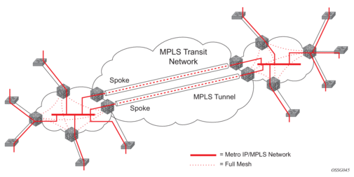
The VPLS standard (RFC 4762, Virtual Private LAN Services Using LDP Signaling) includes provisions for hierarchical VPLS, using point-to-point spoke-SDPs. Two applications have been identified for spoke-SDPs:
- to connect Multi-Tenant Units (MTUs) to PEs in a metro area network
- to interconnect the VPLS nodes of two metro networks
In both applications, the spoke-SDPs serve to improve the scalability of VPLS. While node redundancy is implicit in non-hierarchical VPLS services (using a full mesh of SDPs between PEs), node redundancy for spoke-SDPs needs to be provided separately.
Nokia routers have implemented special features for improving the resilience of hierarchical VPLS instances, in both MTU and inter-metro applications.
3.2.10.1. Spoke SDP Redundancy for Metro Interconnection
When two or more meshed VPLS instances are interconnected by redundant spoke-SDPs (as shown in Figure 66), a loop in the topology results. To remove such a loop from the topology, STP can be run over the SDPs (links) that form the loop, such that one of the SDPs is blocked. As running STP in each and every VPLS in this topology is not efficient, the node includes functionality that can associate a number of VPLSs to a single STP instance running over the redundant SDPs. Therefore, node redundancy is achieved by running STP in one VPLS, and applying the conclusions of this STP to the other VPLS services. The VPLS instance running STP is referred to as the “management VPLS” or M-VPLS.
If the active node fails, STP on the management VPLS in the standby node will change the link states from disabled to active. The standby node will then broadcast a MAC flush LDP control message in each of the protected VPLS instances, so that the address of the newly active node can be relearned by all PEs in the VPLS.
It is possible to configure two management VPLS services, where both VPLS services have different active spokes (this is achieved by changing the path cost in STP). By associating different user VPLSs with the two management VPLS services, load balancing across the spokes can be achieved.
Figure 66: HVPLS with Spoke Redundancy
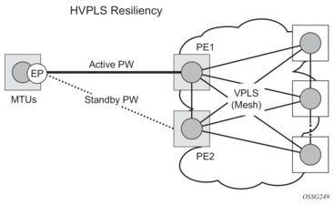
3.2.10.2. Spoke SDP Based Redundant Access
This feature provides the ability to have a node deployed as MTUs (Multi-Tenant Units) to be multi-homed for VPLS to multiple routers deployed as PEs without requiring the use of M-VPLS.
In the configuration example shown in Figure 66, the MTUs have spoke-SDPs to two PE devices. One is designated as the primary and one as the secondary spoke-SDP. This is based on a precedence value associated with each spoke.
The secondary spoke is in a blocking state (both on receive and transmit) as long as the primary spoke is available. When the primary spoke becomes unavailable (due to link failure, PEs failure, and so on), the MTUs immediately switch traffic to the backup spoke and start receiving traffic from the standby spoke. Optional revertive operation (with configurable switch-back delay) is supported. Forced manual switchover is also supported.
To speed up the convergence time during a switchover, MAC flush is configured. The MTUs generate a MAC flush message over the newly unblocked spoke when a spoke change occurs. As a result, the PEs receiving the MAC flush will flush all MACs associated with the impacted VPLS service instance and forward the MAC flush to the other PEs in the VPLS network if “propagate-mac-flush” is enabled.
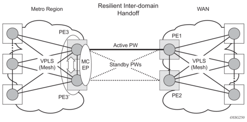
3.2.10.3. Inter-Domain VPLS Resiliency Using Multi-Chassis Endpoints
Inter-domain VPLS refers to a VPLS deployment where sites may be located in different domains. An example of inter-domain deployment can be where different metro domains are interconnected over a Wide Area Network (Metro1-WAN-Metro2) or where sites are located in different autonomous systems (AS1-ASBRs-AS2).
Multi-chassis endpoint (MC-EP) provides an alternate solution that does not require RSTP at the gateway VPLS PEs while still using pseudowires to interconnect the VPLS instances located in the two domains. It is supported in both VPLS and PBB-VPLS on the B-VPLS side.
MC-EP expands the single chassis endpoint based on active-standby pseudowires for VPLS, shown in Figure 67.
Figure 67: HVPLS Resiliency Based on AS Pseudowires
The active-standby pseudowire solution is appropriate for the scenario when only one VPLS PE (MTUs) needs to be dual-homed to two core PEs (PE1 and PE2). When multiple VPLS domains need to be interconnected, the above solution provides a single point of failure at the MTU-s. The example shown in Figure 68 can be used.
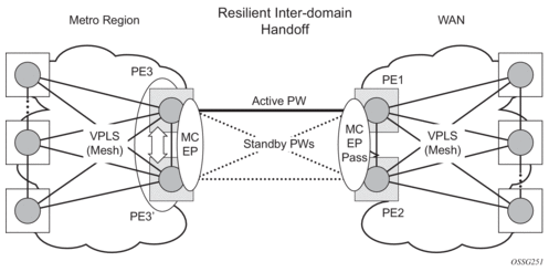
Figure 68: Multi-Chassis Pseudowire Endpoint for VPLS
The two gateway pairs, PE3-PE3’ and PE1-PE2, are interconnected using a full mesh of four pseudowires out of which only one pseudowire is active at any time.
The concept of pseudowire endpoint for VPLS provides multi-chassis resiliency controlled by the MC-EP pair, PE3-PE3’ in this example. This scenario, referred to as multi-chassis pseudowire endpoint for VPLS, provides a way to group pseudowires distributed between PE3 and PE3 chassis in a virtual endpoint that can be mapped to a VPLS instance.
The MC-EP inter-chassis protocol is used to ensure configuration and status synchronization of the pseudowires that belong to the same MC-EP group on PE3 and PE3. Based on the information received from the peer shelf and the local configuration, the master shelf will make a decision on which pseudowire will become active.
The MC-EP solution is built around the following components:
- Multi-chassis protocol used to perform the following functions:
- Selection of master chassis.
- Synchronization of the pseudowire configuration and status.
- Fast detection of peer failure or communication loss between MC-EP peers using either centralized BFD, if configured, or its own keep-alive mechanism.
- T-LDP signaling of pseudowire status:
- Informs the remote PEs about the choices made by the MC-EP pair.
- Pseudowire data plane — Represented by the four pseudowires inter-connecting the gateway PEs.
- Only one of the pseudowires is activated based on the primary/secondary, preference configuration, and pseudowire status. In case of a tie, the pseudowire located on the master chassis will be chosen.
- The rest of the pseudowires are blocked locally on the MC-EP pair and on the remote PEs as long as they implement the pseudowire active/standby status.
3.2.10.3.1. Fast Detection of Peer Failure using BFD
Although the MC-EP protocol has its own keep-alive mechanisms, sharing a common mechanism for failure detection with other protocols (for example, BGP, RSVP-TE) scales better. MC-EP can be configured to use the centralized BFD mechanism.
Similar to other protocols, MC-EP will register with BFD if the bfd-enable command is active under the config>redundancy>multi-chassis>peer>mc-ep context. As soon as the MC-EP application is activated using no shutdown, it tries to open a new BFD session or register automatically with an existing one. The source-ip configuration under redundancy multi-chassis peer-ip is used to determine the local interface while the peer-ip is used as the destination IP for the BFD session. After MC-EP registers with an active BFD session, it will use it for fast detection of MC-EP peer failure. If BFD registration or BFD initialization fails, the MC-EP will keep using its own keep-alive mechanism and it will send a trap to the NMS signaling the failure to register with/open a BFD session.
To minimize operational mistakes and wrong peer interpretation for the loss of BFD session, the following additional rules are enforced when the MC-EP is registering with a BFD session:
- Only the centralized BFD sessions using system or loopback IP interfaces (source-ip parameter) are accepted in order for MC-EP to minimize the false indication of peer loss.
- If the BFD session associated with MC-EP protocol is using a system/loopback interface, the following actions are not allowed under the interface: IP address change, “shutdown”, “no bfd” commands. If one of these actions is required under the interface, the operator needs to disable BFD using the following procedures:
- The no bfd-enable command in the config>redundancy>multi-chassis>peer>mc-ep context — this is the recommended procedure.
- The shutdown command in the config>redundancy>multi-chassis>peer>mc-ep or from under config>redundancy>multi-chassis>peer contexts.
MC-EP keep-alives are still exchanged for the following reasons:
- As a backup; if the BFD session does not come up or is disabled, the MC-EP protocol will use its own keep-alives for failure detection.
- To ensure the database is cleared if the remote MC-EP peer is shut down or misconfigured (each x seconds; one second suggested as default).
If MC-EP deregisters with BFD using the no bfd-enable command, the following processing steps occur:
- The local peer indicates to the MC-EP peer that the local BFD is being disabled using the MC-EP peer-config-TLV fields ([BFD local: BFD remote]). This is done to avoid the wrong interpretation of the BFD session loss.
- The remote peer acknowledges reception indicating through the same peer-config-TLV fields that it is deregistering with the BFD session.
- Both MC-EP peers deregister and use only keep-alives for failure detection.
- There should be no pseudowire status change during this process.
Traps are sent when the status of the monitoring of the MC-EP session through BFD changes in the following instances:
- When red/mc/peer is no shutdown and BFD is not enabled, a notification is sent indicating BFD is not monitoring the MC-EP peering session.
- When BFD changes to open, a notification is sent indicating BFD is monitoring the MC-EP peering session.
- When BFD changes to down/close, a notification is sent indicating BFD is not monitoring the MC-EP peering session.
3.2.10.3.2. MC-EP Passive Mode
The MC-EP mechanisms are built to minimize the possibility of loops. It is possible that human error could create loops through the VPLS service. One way to prevent loops is to enable the MAC move feature in the gateway PEs (PE3, PE3', PE1, and PE2).
An MC-EP passive mode can also be used on the second PE pair, PE1 and PE2, as a second layer of protection to prevent any loops from occurring if the operator introduces operational errors on the MC-EP PE3, PE3 pair. An example is shown in Figure 69.
Figure 69: MC-EP in Passive Mode
When in passive mode, the MC-EP peers stay dormant as long as one active pseudowire is signaled from the remote end. If more than one pseudowire belonging to the passive MC-EP becomes active, the PE1 and PE2 pair applies the MC-EP selection algorithm to select the best choice and blocks all others. No signaling is sent to the remote pair to avoid flip-flop behavior. A trap is generated each time MC-EP in passive mode activates. Every occurrence of this kind of trap should be analyzed by the operator as it is an indication of possible misconfiguration on the remote (active) MC-EP peering.
For the MC-EP passive mode to work, the pseudowire status signaling for active/standby pseudowires should be enabled. This requires the following CLI configurations:
For the remote MC-EP PE3, PE3 pair:
config>service>vpls>endpoint# no suppress-standby-signaling
When MC-EP passive mode is enabled on the PE1 and PE2 pair, the following command is always enabled internally, regardless of the actual configuration:
config>service>vpls>endpoint no ignore-standby-signaling
3.2.10.4. Support for Single Chassis Endpoint Mechanisms
In cases of SC-EP, there is a consistency check to ensure that the configuration of the member pseudowires is the same. For example, mac-pining, mac-limit, and ignore standby signaling must be the same. In the MC-EP case, there is no consistency check between the member endpoints located on different chassis. The operator must carefully verify the configuration of the two endpoints to ensure consistency.
The following rules apply for suppress-standby-signaling and ignore-standby parameters:
- Regular MC-EP mode (non-passive) will follow the suppress-standby-signaling and ignore-standby settings from the related endpoint configuration.
- For MC-EP configured in passive mode, the following settings will be used, regardless of previous configuration: suppress-standby-sig and no ignore-standby-sig. It is expected that when passive mode is used at one side, the regular MC-EP side will activate signaling with no suppress-stdby-sig.
- When passive mode is configured in just one of the nodes in the MC-EP peering, the other node will be forced to change to passive mode. A trap is sent to the operator to signal the wrong configuration.
This section also describes how the main mechanisms used for single chassis endpoint are adapted for the MC-EP solution.
3.2.10.4.1. MAC Flush Support in MC-EP
In an MC-EP scenario, failure of a pseudowire or gateway PE will determine activation of one of the next best pseudowires in the MC-EP group. This section describes the MAC flush procedures that can be applied to ensure blackhole avoidance.
Figure 70 shows a pair of PE gateways (PE3 and PE3) running MC-EP toward PE1 and PE2 where F1 and F2 are used to indicate the possible direction of the MAC flush, signaled using T-LDP MAC withdraw message. PE1 and PE2 can only use regular VPLS pseudowires and do not have to use an MC-EP or a regular pseudowire endpoint.
Figure 70: MAC Flush in the MC-EP Solution
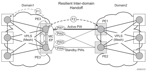
Regular MAC flush behavior will apply for the LDP MAC withdraw sent over the T-LDP sessions associated with the active pseudowire in the MC-EP; for example, PE3 to PE1. That includes any Topology Change Notification (TCN) events or failures associated with SAPs or pseudowires not associated with the MC-EP.
The following MAC flush behaviors apply to changes in the MC-EP pseudowire selection:
- If the local PW2 becomes active on PE3:
- On PE3, the MACs mapped to PW1 are moved to PW2.
- A T-LDP flush-all-but-mine message is sent toward PE2 in the F2 direction and is propagated by PE2 in the local VPLS mesh.
- No MAC flush is sent in the F1 direction from PE3.
- If one of the pseudowires on the pair PE3 becomes active; for example, PW4:
- On PE3, the MACs mapped to PW1 are flushed, the same as for a regular endpoint.
- PE3 must be configured with send-flush-on-failure to send a T-LDP flush-all-from-me message toward VPLS mesh in the F1 direction.
- PE3 sends a T-LDP flush-all-but-mine message toward PE2 in the F2 direction, which is propagated by PE2 in the local VPLS mesh. When MC-EP is in passive mode and the first spoke becomes active, a no mac flush-all-but-mine message will be generated.
3.2.10.4.2. Block-on-Mesh-Failure Support in MC-EP Scenario
The following rules describe how the block-on-mesh-failure operates with the MC-EP solution (see Figure 70):
- If PE3 does not have any forwarding path toward Domain1 mesh, it should block both PW1 and PW2 and inform PE3 so one of its pseudowires can be activated.
- To allow the use of block-on-mesh-failure for MC-EP, a block-on-mesh-failure parameter can be specified in the config>service>vpls>endpoint context with the following rules:
- The default is no block-on-mesh-failure to allow for easy migration.
- For a spoke-SDP to be added under an endpoint, the setting for its block-on-mesh-failure parameter must be in synchronization with the endpoint parameter.
- After the spoke-SDP is added to an endpoint, the configuration of its block-on-mesh-failure parameter is disabled. A change in endpoint configuration for the block-on-mesh-failure parameter is propagated to the individual spoke-SDP configuration.
- When a spoke-SDP is removed from the endpoint group, it will inherit the last configuration from the endpoint parameter.
- Adding an MC-EP under the related endpoint configuration does not affect the above behavior.
Before Release 7.0, the block-on-mesh-failure command could not be enabled under config>service>vpls>endpoint context. For a spoke-SDP to be added to an (single-chassis) endpoint, its block-on-mesh-failure had to be disabled (config>service>vpls>spoke-sdp>no block-on-mesh-failure). Then, the configuration of block-on-mesh-failure under a spoke-SDP is blocked. - If block-on-mesh-failure is enabled on PE1 and PE2, these PEs will signal pseudowire standby status toward the MC-EP PE pair. PE3 and PE3 should consider the pseudowire status signaling from remote PE1 and PE2 when making the selection of the active pseudowire.
3.2.10.4.3. Support for Force Spoke SDP in MC-EP
In a regular (single chassis) endpoint scenario, the following command can be used to force a specific SDP binding (pseudowire) to become active:
tools perform service id service-id endpoint endpoint-name force
In the MC-EP case, this command has a similar effect when there is a single forced SDP binding in an MC-EP. The forced SDP binding (pseudowire) will be elected as active.
However, when the command is run at the same time as both MC-EP PEs, when the endpoints belong to the same MC-EP, the regular MC-EP selection algorithm (for example, the operational status ⇒precedence value) will be applied to determine the winner.
3.2.10.4.4. Revertive Behavior for Primary Pseudowires in an MC-EP
For a single-chassis endpoint, a revert-time command is provided under the VPLS endpoint. Refer to the VPLS Service Configuration Command Reference for syntax and command usage information.
In a regular endpoint, the revert-time setting affects just the pseudowire defined as primary (precedence 0). For a failure of the primary pseudowire followed by restoration, the revert-timer is started. After it expires, the primary pseudowire takes the active role in the endpoint. This behavior does not apply for the case when both pseudowires are defined as secondary; that is, if the active secondary pseudowire fails and is restored, it will stay in standby until a configuration change or a force command occurs.
In the MC-EP case, the revertive behavior is supported for pseudowire defined as primary (precedence 0). The following rules apply:
- The revert-time setting under each individual endpoint control the behavior of the local primary pseudowire if one is configured under the local endpoint.
- The secondary pseudowires behave as in the regular endpoint case.
3.2.10.5. Using B-VPLS for Increased Scalability and Reduced Convergence Times
The PBB-VPLS solution can be used to improve scalability of the solution and to reduce convergence time. If PBB-VPLS is deployed starting at the edge PEs, the gateway PEs will contain only B-VPLS instances. The MC-EP procedures described for regular VPLS apply.
PBB-VPLS can also be enabled just on the gateway MC-EP PEs, as shown in Figure 71.
Figure 71: MC-EP with B-VPLS
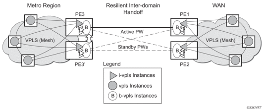
Multiple I-VPLS instances may be used to represent in the gateway PEs the customer VPLS instances using the PBB-VPLS M:1 model described in the PBB section. A backbone VPLS (B-VPLS) is used in this example to administer the resiliency for all customer VPLS instances at the domain borders. Just one MC-EP is required to be configured in the B-VPLS to address hundreds or even thousands of customer VPLS instances. If load balancing is required, multiple B-VPLS instances may be used to ensure even distribution of the customers across all the pseudowires interconnecting the two domains. In this example, four B-VPLSs will be able to load share the customers across all four possible pseudowire paths.
The use of MC-EP with B-VPLS is strictly limited to cases where VPLS mesh exists on both sides of a B-VPLS. For example, active/standby pseudowires resiliency in the I-VPLS context where PE3 and PE3’ are PE-rs cannot be used because there is no way to synchronize the active/standby selection between the two domains.
For a similar reason, MC-LAG resiliency in the I-VPLS context on the gateway PEs participating in the MC-EP (PE3 and PE3’) should not be used.
For the PBB topology in Figure 71, block-on-mesh-failure in the I-VPLS domain will not have any effect on the B-VPLS MC-EP side. That is because mesh failure in one I-VPLS should not affect other I-VPLSs sharing the same B-VPLS.
3.2.10.6. MAC Flush Additions for PBB VPLS
The scenario shown in Figure 72 is used to define the blackholing problem in PBB-VPLS using MC-EP.
Figure 72: MC-EP with B-VPLS Failure Scenario
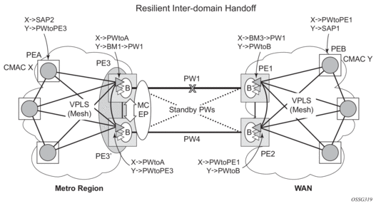
In the topology shown in Figure 72, PEA and PEB are regular VPLS PEs participating in the VPLS mesh deployed in the metro and WAN region, respectively. As the traffic flows between CEs with CMAC X and CMAC Y, the FDB entries in PEA, PE3, PE1 and PEB are installed. An LDP flush-all-but-mine message will be sent from PE3 to PE2 to clear the B-VPLS FDBs. The traffic between CMAC X and CMAC Y will be blackholed as long as the entries from the VPLS and I-VPLS FDBs along the path are not removed. This may take as long as 300 seconds, the usual aging timer used for MAC entries in a VPLS FDB.
A MAC flush is required in the I-VPLS space from PBB PEs to PEA and PEB to avoid blackholing in the regular VPLS space.
In the case of a regular VPLS, the following procedure is used:
- PE3 sends a flush-all-from-me message toward its local blue I-VPLS mesh to PE3 and PEA when its MC-EP becomes disabled.
- PE3 sends a flush-all-but-mine message on the active PW4 to PE2, which is then propagated by PE2 (propagate-mac-flush must be on) to PEB in the WAN I-VPLS mesh.
For consistency, a similar procedure is used for the B-VPLS case as shown in Figure 73.
Figure 73: MC-EP with B-VPLS MAC Flush Solution
In this example, the MC-EP activates B-VPLS PW4 because of either a link/node failure or because of an MC-EP selection re-run that affected the previously active PW1. As a result, the endpoint on PE3 containing PW1 goes down.
The following steps apply:
- PE3 sends, in the local I-VPLS context, an LDP flush-all-from-me message (marked with F1) to PEA and to the other regular VPLS PEs, including PE3. The following command enables this behavior on a per I-VPLS basis: config>service>vpls ivpls>send-flush-on-bvpls-failure.
- Result: PEA, PE3, and the other local VPLS PEs in the metro clear the VPLS FDB entries associated with PW to PE3.
- PE3 clears the entries associated with PW1 and sends, in the B-VPLS context, an LDP flush-all-but-mine message (marked with F2) toward PE2 on the active PW4.
- Result: PE2 clears the B-VPLS FDB entries not associated with PW4.
- PE2 propagates the MAC flush-all-but-mine (marked with F3) from B-VPLS in the related I-VPLS contexts toward all participating VPLS PEs; for example, in the blue I-VPLS to PEB, PE1. It also clears all the CMAC entries associated with I-VPLS pseudowires.The following command enables this behavior on a per I-VPLS basis:config>service>vpls ivpls>propagate-mac-flush-from-bvpls
- Result: PEB, PE1, and the other local VPLS PEs in the WAN clear the VPLS FDB entries associated with PW to PE2.
- This command does not control the propagation in the related I-VPLS of the B-VPLS LDP MAC flush containing a PBB TLV (BMAC and ISID list).
- Similar to regular VPLS, LDP signaling of the MAC flush will follow the active topology; for example, no MAC flush will be generated on standby pseudowires.
Other failure scenarios are addressed using the same or a subset of the above steps:
- If the pseudowire (PW2) in the same endpoint with PW1 becomes active instead of PW4, there will be no MAC flush of F1 type.
- If the pseudowire (PW3) in the same endpoint becomes active instead of PW4, the same procedure applies.
For an SC/MC endpoint configured in a B-VPLS, failure/deactivation of the active pseudowire member always generates a local MAC flush of all the BMAC associated with the pseudowire. It never generates a MAC move to the newly active pseudowire even if the endpoint stays up. That is because in SC-EP/MC-EP topology, the remote PE might be the terminating PBB PE and may not be able to reach the BMAC of the other remote PE. Therefore, connectivity between them exists only over the regular VPLS mesh.
For the same reasons, Nokia recommends that static BMAC not be used on SC/MC endpoints.
3.2.11. VPLS Access Redundancy
A second application of hierarchical VPLS is using MTUs that are not MPLS-enabled that must have Ethernet links to the closest PE node. To protect against failure of the PE node, an MTU can be dual-homed and have two SAPs on two PE nodes.
There are several mechanisms that can be used to resolve a loop in an access circuit; however, from an operations perspective, they can be subdivided into two groups:
- STP-based access, with or without M-VPLS.
- Non-STP based access using mechanisms such as MC-LAG, MC-APS, MC-Ring.
3.2.11.1. STP-based Redundant Access to VPLS
Figure 74: Dual-homed MTUs in Two-Tier Hierarchy H-VPLS
In the configuration shown in Figure 74, STP is activated on the MTU and two PEs in order to resolve a potential loop. STP only needs to run in a single VPLS instance, and the results of the STP calculations are applied to all VPLSs on the link.
In this configuration, the scope of the STP domain is limited to MTU and PEs, while any topology change needs to be propagated in the whole VPLS domain including mesh SDPs. This is done by using so-called MAC-flush messages defined by RFC 4762. In the case of STP as an loop resolution mechanism, every TCN received in the context of an STP instance is translated into an LDP-MAC address withdrawal message (also referred to as a MAC-flush message) requesting to clear all FDB entries except the ones learned from the originating PE. Such messages are sent to all PE peers connected through SDPs (mesh and spoke) in the context of VPLS services, which are managed by the specified STP instance.
3.2.11.2. Redundant Access to VPLS Without STP
The Nokia implementation also includes alternative methods for providing a redundant access to Layer 2 services, such as MC-LAG, MC-APS, or MC-Ring. Also in this case, the topology change event needs to be propagated into the VPLS topology in order to provide fast convergence. The topology change propagation and its corresponding MAC flush processing in a VPLS service without STP is described in Dual Homing to a VPLS Service.
3.2.12. Object Grouping and State Monitoring
This feature introduces a generic operational group object that associates different service endpoints (pseudowires, SAPs, IP interfaces) located in the same or in different service instances.
The operational group status is derived from the status of the individual components using certain rules specific to the application using the feature. A number of other service entities, the monitoring objects, can be configured to monitor the operational group status and to perform certain actions as a result of status transitions. For example, if the operational group goes down, the monitoring objects will be brought down.
3.2.12.1. VPLS Applicability — Block on VPLS a Failure
This feature is used in VPLS to enhance the existing BGP MH solution by providing a block-on-group failure function similar to the block-on-mesh failure feature implemented for LDP VPLS. On the PE selected as the Designated Forwarder (DF), if the rest of the VPLS endpoints fail (pseudowire spokes/pseudowire mesh and/or SAPs), there is no path forward for the frames sent to the MH site selected as DF. The status of the VPLS endpoints, other than the MH site, is reflected by bringing down/up the objects associated with the MH site.
Support for the feature is provided initially in VPLS and B-VPLS instance types for LDP VPLS, with or without BGP-AD and for BGP VPLS. The following objects may be placed as components of an operational group: BGP VPLS pseudowires, SAPs, spoke-pseudowire, BGP-AD pseudowires. The following objects are supported as monitoring objects: BGP MH site, individual SAP, spoke-pseudowire.
The following rules apply:
- An object can only belong to one group at a time.
- An object that is part of a group cannot monitor the status of any group.
- An object that monitors the status of a group cannot be part of any group.
- An operational group may contain any combination of member types: SAP, spoke-pseudowire, BGP-AD or BGP VPLS pseudowires.
- An operational group may contain members from different VPLS service instances.
- Objects from different services may monitor the operational group.
- The operational group feature may co-exist in parallel with the block-on-mesh failure feature as long as they are running in different VPLS instances.
There are two steps involved in enabling the block-on-mesh failure feature in a VPLS scenario:
- Identify a set of objects whose forwarding state should be considered as a whole group, then group them under an operational group using the oper-group CLI command.
- Associate other existing objects (clients) with the oper-group command using the monitor-group CLI command; its forwarding state will be derived from the related operational group state.
The status of the operational group (oper-group) is dictated by the status of one or more members according to the following rule:
- The oper-group goes down if all the objects in the oper-group go down; the oper-group comes up if at least one of the components is up.
- An object in the oper-group is considered down if it is not forwarding traffic in at least one direction. That could be because the operational state is down or the direction is blocked through some resiliency mechanisms.
- If an oper-group is configured but no members are specified yet, its status is considered up. As soon as the first object is configured, the status of the oper-group is dictated by the status of the provisioned members.
- For BGP-AD or BGP VPLS pseudowires associated with the oper-group (under the config>service-vpls>bgp>pw-template-binding context), the status of the oper-group is down as long as the pseudowire members are not instantiated (auto-discovered and signaled).
A simple configuration example is described for the case of a BGP VPLS mesh used to interconnect different customer locations. If we assume a customer edge (CE) device is dual-homed to two PEs using BGP MH, the following configuration steps apply:
- The oper-group bgp-vpls-mesh is created.
- The BGP VPLS mesh is added to the bgp-vpls-mesh group through the pseudowire template used to create the BGP VPLS mesh.
- The BGP MH site defined for the access endpoint is associated with the bgp-vpls-mesh group; its status from now on will be influenced by the status of the BGP VPLS mesh.
A simple configuration example follows:
3.2.13. MAC Flush Message Processing
The previous sections described operating principles of several redundancy mechanisms available in the context of VPLS service. All of them rely on MAC flush messages as a tool to propagate topology change in a context of the specified VPLS. This section summarizes basic rules for generation and processing of these messages.
As described in respective sections, the 7450 ESS, 7750 SR, and 7950 XRS support two types of MAC flush message: flush-all-but-mine and flush-mine. The main difference between these messages is the type of action they signal. Flush-all-but-mine messages request clearing of all FDB entries that were learned from all other LDP peers except the originating PE. This type is also defined by RFC 4762 as an LDP MAC address withdrawal with an empty MAC address list.
Flush-all-mine messages request clearing all FDB entries learned from the originating PE. This means that this message has the opposite effect of the flush-all-but-mine message. This type is not included in the RFC 4762 definition and it is implemented using vendor-specific TLV.
The advantages and disadvantages of the individual types should be apparent from examples in the previous section. The description here summarizes actions taken on reception and the conditions under which individual messages are generated.
Upon reception of MAC flush messages (regardless of the type), an SR-series PE will take the following actions:
- Clears FDB entries of all indicated VPLS services conforming to the definition.
- Propagates the message (preserving the type) to all LDP peers, if the propagate-mac-flush flag is enabled at the corresponding VPLS level.
The flush-all-but-mine message is generated under the following conditions:
- The flush-all-but-mine message is received from the LDP peer and the propagate-mac-flush flag is enabled. The message is sent to all LDP peers in the context of the VPLS service it was received.
- The TCN message in a context of STP instance is received. The flush-all-but-mine message is sent to all LDP peers connected with spoke and mesh SDPs in a context of VPLS service controlled by the specified STP instance (based on M-VPLS definition). If all LDP peers are in the STP domain, that is, the M-VPLS and the uVPLS (user VPLS) both have the same topology, the router will not send any flush-all-but-mine message. If the router has uVPLS LDP peers outside the STP domain, the router will send flush-all-but-mine messages to all its uVPLS peers.

Note: The 7750 SR will not send a withdrawal if the M-VPLS does not contain a mesh SDP. A mesh SDP must be configured in the M-VPLS to send withdrawals.
- The flush-all-but-mine message is generated when switchover between spoke-SDPs of the same endpoint occurs. The message is sent to the LDP peer connected through the newly active spoke-SDP.
The flush-mine message is generated under the following conditions:
- The flush-mine message is received from the LDP peer and the propagate-mac-flush flag is enabled. The message is sent to all LDP peers in the context of the VPLS service it was received.
- The flush-mine message is generated when a SAP or SDP transitions from operationally up to an operationally down state and the send-flush-on-failure flag is enabled in the context of the specified VPLS service. The message is sent to all LDP peers connected in the context of the specified VPLS service. The send-flush-on-failure flag is blocked in M-VPLS and is only allowed to be configured in a VPLS service managed by M-VPLS. This is to prevent both messages being sent at the same time.
- The flush-mine message is generated when an MC-LAG SAP or MC-APS SAP transitions from an operationally up state to an operationally down state. The message is sent to all LDP peers connected in the context of the specified VPLS service.
- The flush-mine message is generated when an MC-Ring SAP transitions from operationally up to an operationally down state or when MC-Ring SAP transitions to slave state. The message is sent to all LDP peers connected in the context of the specified VPLS service.
3.2.13.1. Dual Homing to a VPLS Service
Figure 75: Dual-homed CE Connection to VPLS
Figure 75 shows a dual-homed connection to VPLS service (PE-A, PE-B, PE-C, PE-D) and operation in case of link failure (between PE-C and L2-B). Upon detection of a link failure, PE-C will send MAC-address-withdraw messages, which will indicate to all LDP peers that they should flush all MAC addresses learned from PE-C. This will lead to a broadcasting of packets addressing affected hosts and relearning in case an alternative route exists.
The message described here is different than the message described in RFC 4762, Virtual Private LAN Services Using LDP Signaling. The difference is in the interpretation and action performed in the receiving PE. According to the standard definition, upon receipt of a MAC withdraw message, all MAC addresses, except the ones learned from the source PE, are flushed. This section specifies that all MAC addresses learned from the source are flushed. This message has been implemented as an LDP address withdraw message with vendor-specific type, length, and value (TLV), and is called the flush-all-from-me message.
The RFC 4762 compliant message is used in VPLS services for recovering from failures in STP (Spanning Tree Protocol) topologies. The mechanism described in this section represents an alternative solution.
The advantage of this approach (as compared to STP-based methods) is that only the affected MAC addresses are flushed and not the full forwarding database. While this method does not provide a mechanism to secure alternative loop-free topology, the convergence time is dependent on the speed that the specified CE device will open an alternative link (L2-B switch in Figure 75) as well as on the speed that PE routers will flush their FDB.
In addition, this mechanism is effective only if PE and CE are directly connected (no hub or bridge) as the mechanism reacts to the physical failure of the link.
3.2.13.2. MC-Ring and VPLS
The use of multi-chassis ring control in a combination with the plain VPLS SAP is supported by the FDB in individual ring nodes, in case the link (or ring node) failure cannot be cleared on the 7750 SR or 7950 XRS.
This combination is not easily blocked in the CLI. If configured, the combination may be functional but the switchover times will be proportional to MAC aging in individual ring nodes and/or to the relearning rate due to downstream traffic.
Redundant plain VPLS access in ring configurations, therefore, exclude corresponding SAPs from the multi-chassis ring operation. Configurations such as M-VPLS can be applied.
3.2.14. ACL Next-Hop for VPLS
The ACL next-hop for VPLS feature enables an ACL that has a forward to a SAP or SDP action specified to be used in a VPLS service to direct traffic with specific match criteria to a SAP or SDP. This allows traffic destined for the same gateway to be split and forwarded differently based on the ACL.
Figure 76: Application 1 Diagram
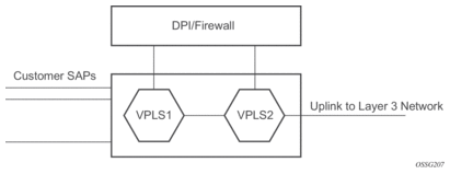
Policy routing is a popular tool used to direct traffic in Layer 3 networks. As Layer 2 VPNs become more popular, especially in network aggregation, policy forwarding is required. Many providers are using methods such as DPI servers, transparent firewalls, or Intrusion Detection/Prevention Systems (IDS/IPS). Since these devices are bandwidth limited, providers want to limit traffic forwarded through them. In the setup shown in Figure 76, a mechanism is required to direct some traffic coming from a SAP to the DPI without learning, and other traffic coming from the same SAP directly to the gateway uplink-based learning.
This feature will allow the provider to create a filter that will forward packets to a specific SAP or SDP. The packets are then forwarded to the destination SAP regardless of learned destination. The SAP can either terminate a Layer 2 firewall, perform deep packet inspection (DPI) directly, or may be configured to be part of a cross-connect bridge into another service. This will be useful when running the DPI remotely using VLLs. If an SDP is used, the provider can terminate it in a remote VPLS or VLL service where the firewall is connected. The filter can be configured under a SAP or SDP in a VPLS service. All packets (unicast, multicast, broadcast, and unknown) can be delivered to the destination SAP/SDP.
The filter may be associated with SAPs/SDPs belonging to a VPLS service only if all actions in the ACL forward to SAPs/SDPs that are within the context of that VPLS. Other services do not support this feature. An ACL that contains this feature is allowed, but the system will drop any packet that matches an entry with this action.
3.2.15. SDP Statistics for VPLS and VLL Services
The simple three-node network in Figure 77 shows two MPLS SDPs and one GRE SDP defined between the nodes. These SDPs connect VPLS1 and VPLS2 instances that are defined in the three nodes. With this feature, the operator will have local CLI-based as well as SNMP-based statistics collection for each VC used in the SDPs. This will allow for traffic management of tunnel usage by the different services and with aggregation of the total tunnel usage.
Figure 77: SDP Statistics for VPLS and VLL Services
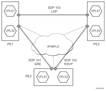
SDP statistics allow providers to bill customers on a per-SDP per-byte basis. This destination-based billing model can be used by providers with a variety of circuit types and have different costs associated with the circuits. An accounting file allows the collection of statistics in bulk.
3.2.16. BGP Auto-Discovery for LDP VPLS
BGP Auto-Discovery (BGP AD) for LDP VPLS is a framework for automatically discovering the endpoints of a Layer 2 VPN, offering an operational model similar to that of an IP VPN. This allows carriers to leverage existing network elements and functions, including but not limited to, route reflectors and BGP policies to control the VPLS topology.
BGP AD complements an already established and well-deployed Layer 2 VPN signaling mechanism target LDP, providing one-touch provisioning for LDP VPLS, where all the related PEs are discovered automatically. The service provider may make use of existing BGP policies to regulate the exchanges between PEs in the same, or in different, autonomous system (AS) domains. The addition of BGP AD procedures does not require carriers to uproot their existing VPLS deployments nor to change the signaling protocol.
3.2.16.1. BGP AD Overview
The BGP protocol establishes neighbor relationships between configured peers. An open message is sent after the completion of the three-way TCP handshake. This open message contains information about the BGP peer sending the message. This message contains Autonomous System Number (ASN), BGP version, timer information, and operational parameters, including capabilities. The capabilities of a peer are exchanged using two numerical values: the Address Family Identifier (AFI) and Subsequent Address Family Identifier (SAFI). These numbers are allocated by the Internet Assigned Numbers Authority (IANA). BGP AD uses AFI 65 (L2VPN) and SAFI 25 (BGP VPLS). The complete list of allocations are at: http://www.iana.org/assignments/address-family-numbers and SAFI http://www.iana.org/assignments/safi-namespace.
3.2.16.2. Information Model
Following the establishment of the peer relationship, the discovery process begins as soon as a new VPLS service instance is provisioned on the PE.
Two VPLS identifiers are used to indicate the VPLS membership and the individual VPLS instance:
- VPLS-ID — Membership information, and unique network-wide identifier; the same value is assigned for all VPLS switch instances (VSIs) belonging to the same VPLS. VPLS-ID is encodable and carried as a BGP extended community in one of the following formats:
- A two-octet AS-specific extended community
- An IPv4 address-specific extended community
- VSI-ID — The unique identifier for each individual VSI, built by concatenating a route distinguisher (RD) with a 4-byte identifier (usually the system IP of the VPLS PE), encoded and carried in the corresponding BGP NLRI.
To advertise this information, BGP AD employs a simplified version of the BGP VPLS NLRI where just the RD and the next 4 bytes are used to identify the VPLS instance. There is no need for Label Block and Label Size fields as T-LDP will signal the service labels later on.
The format of the BGP AD NLRI is very similar to the one used for IP VPN, as shown in Figure 78. The system IP may be used for the last 4 bytes of the VSI ID, further simplifying the addressing and the provisioning process.
Figure 78: BGP AD NLRI versus IP VPN NLRI
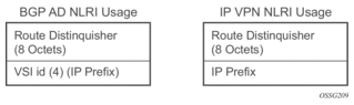
Network Layer Reachability Information (NLRI) is exchanged between BGP peers indicating how to reach prefixes. The NLRI is used in the Layer 2 VPN case to tell PE peers how to reach the VSI, rather than specific prefixes. The advertisement includes the BGP next hop and a route target (RT). The BGP next hop indicates the VSI location and is used in the next step to determine which signaling session is used for pseudowire signaling. The RT, also coded as an extended community, can be used to build a VPLS full mesh or an HVPLS hierarchy through the use of BGP import/export policies.
BGP is only used to discover VPN endpoints and the corresponding far-end PEs. It is not used to signal the pseudowire labels. This task remains the responsibility of targeted-LDP (T-LDP).
3.2.16.3. FEC Element for T-LDP Signaling
Two LDP FEC elements are defined in RFC 4447, PW Setup & Maintenance Using LDP. The original pseudowire-ID FEC element 128 (0x80) employs a 32-bit field to identify the virtual circuit ID and was used extensively in the initial VPWS and VPLS deployments. The simple format is easy to understand, but does not provide the required information model for BGP auto-discovery function. To support BGP AD and other new applications, a new Layer 2 FEC element, the generalized FEC (0x81), is required.
The generalized pseudowire-ID FEC element has been designed for auto-discovery applications. It provides a field, the address group identifier (AGI), that is used to signal the membership information from the VPLS-ID. Separate address fields are provided for the source and target address associated with the VPLS endpoints, called the Source Attachment Individual Identifier (SAII) and Target Attachment Individual Identifier (TAII), respectively. These fields carry the VSI ID values for the two instances that are to be connected through the signaled pseudowire.
The detailed format for FEC 129 is shown in Figure 79.
Figure 79: Generalized Pseudowire-ID FEC Element
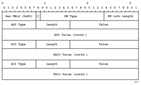
Each of the FEC fields are designed as a sub-TLV equipped with its own type and length, providing support for new applications. To accommodate the BGP AD information model, the following FEC formats are used:
- AGI (type 1) is identical in format and content to the BGP extended community attribute used to carry the VPLS-ID value.
- Source AII (type 1) is a 4-byte value to carry the local VSI-ID (outgoing NLRI minus the RD).
- Target AII (type 1) is a 4-byte value to carry the remote VSI-ID (incoming NLRI minus the RD).
3.2.16.4. BGP-AD and Target LDP (T-LDP) Interaction
BGP is responsible for discovering the location of VSIs that share the same VPLS membership. LDP protocol is responsible for setting up the pseudowire infrastructure between the related VSIs by exchanging service-specific labels between them.
Once the local VPLS information is provisioned in the local PE, the related PEs participating in the same VPLS are identified through BGP AD exchanges. A list of far-end PEs is generated and will trigger the creation, if required, of the necessary T-LDP sessions to these PEs and the exchange of the service-specific VPN labels. The steps for the BGP AD discovery process and LDP session establishment and label exchange are shown in Figure 80.
Figure 80: BGP-AD and T-LDP Interaction
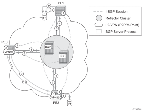
Key:
- Establish I-BGP connectivity RR.
- Configure VPN (10) on edge node (PE3).
- Announce VPN to RR using BGP-AD.
- Send membership update to each client of the cluster.
- LDP exchange or inbound FEC filtering (IFF) of non-match or VPLS down.
- Configure VPN (10) on edge node (PE2).
- Announce VPN to RR using BGP-AD.
- Send membership update to each client of the cluster.
- LDP exchange or inbound FEC filtering (IFF) of non-match or VPLS down.
- Complete LDP bidirectional pseudowire establishment FEC 129.
3.2.16.5. SDP Usage
Service Access Points (SAPs) are linked to transport tunnels using Service Distribution Points (SDPs). The service architecture allows services to be abstracted from the transport network.
MPLS transport tunnels are signaled using the Resource Reservation Protocol (RSVP-TE) or by the Label Distribution Protocol (LDP). The capability to automatically create an SDP only exists for LDP-based transport tunnels. Using a manually provisioned SDP is available for both RSVP-TE and LDP transport tunnels. Refer to the appropriate 7450 ESS, 7750 SR, 7950 XRS, and VSR MPLS Guide for more information about MPLS, LDP, and RSVP.
GRE transport tunnels use GRE encapsulation and can be used with manually provisioned or auto created SDPs.
3.2.16.6. Automatic Creation of SDPs
When BGP AD is used for LDP VPLS, with an LDP or GRE transport tunnel, there is no requirement to manually create an SDP. The LDP or GRE SDP can be automatically instantiated using the information advertised by BGP AD. This simplifies the configuration on the service node.
The use of an automatically created GRE tunnel is enabled by creating the PW template used within the service with the parameter auto-gre-sdp. The GRE SDP and SDP binding is created after a matching BGP route has been received.
Enabling LDP on the IP interfaces connecting all nodes between the ingress and the egress builds transport tunnels based on the best IGP path. LDP bindings are automatically built and stored in the hardware. These entries contain an MPLS label pointing to the best next hop along the best path toward the destination.
When two endpoints need to connect and no SDP exists, a new SDP will automatically be constructed. New services added between two endpoints that already have an automatically created SDP will be immediately used; no new SDP will be constructed. The far-end information is learned from the BGP next hop information in the NLRI. When services are withdrawn with a BGP_Unreach-NLRI, the automatically established SDP will remain up while at least one service is connected between those endpoints. An automatically created SDP will be removed and the resources released when the only or last service is removed.
The service provider has the option of associating the auto-discovered SDP with a split horizon group using the pw-template-binding option, to control the forwarding between pseudowires and to prevent Layer 2 service loops.
An auto-discovered SDP using a pw-template-binding without a split horizon group configured will have similar traffic flooding behavior as a spoke-SDP.
3.2.16.7. Manually Provisioned SDP
The carrier is required to manually provision the SDP if they create transport tunnels using RSVP-TE. Operators have the option to choose a manually configured SDP if they use LDP as the tunnel signaling protocol. The functionality is the same regardless of the signaling protocol.
Creating a BGP AD-enabled VPLS service on an ingress node with the manually provisioned SDP option causes the tunnel manager to search for an existing SDP that connects to the far-end PE. The far-end IP information is learned from the BGP next hop information in the NLRI. If a single SDP exists to that PE, it is used. If no SDP is established between the two endpoints, the service will remain down until a manually configured SDP becomes active.
When multiple SDPs exist between two endpoints, the tunnel manager will select the appropriate SDP. The algorithm will prefer SDPs with the best (lower) metric. If there are multiple SDPs with equal metrics, the operational state of the SDPs with the best metric will be considered. If the operational state is the same, the SDP with the higher SDP-ID will be used. If an SDP with a preferred metric is found with an operational state that is not active, the tunnel manager will flag it as ineligible and restart the algorithm.
3.2.16.8. Automatic Instantiation of Pseudowires (SDP Bindings)
The choice of manual or auto-provisioned SDPs has limited impact on the amount of required provisioning. Most of the savings are achieved through the automatic instantiation of the pseudowire infrastructure (SDP bindings). This is achieved for every auto-discovered VSI through the use of the pseudowire template concept. Each VPLS service that uses BGP AD contains the pw-template-binding option defining specific Layer 2 VPN parameters. This command references a PW template, which defines the pseudowire parameters. The same PW template may be referenced by multiple VPLS services. As a result, changes to these pseudowire templates have to be treated with caution as they may impact many customers simultaneously.
The Nokia implementation provides for safe handling of pseudowire templates. Changes to the pseudowire templates are not automatically propagated. Tools are provided to evaluate and distribute the changes. The following command is used to distribute changes to a PW template at the service level to one or all services that use that template:
PERs-4# tools perform service id 300 eval-pw-template 1 allow-service-impact
If the service ID is omitted, all services will be updated. The type of change made to the PW template will influence how the service is impacted:
- Adding or removing a split-horizon-group will cause the router to destroy the original object and re-create it using the new value.
- Changing parameters in the vc-type {ether | vlan} command requires LDP to re-signal the labels.
Both of these changes are service affecting. Other changes will not be service affecting.
3.2.16.9. Mixing Statically Configured and Auto-Discovered Pseudowires in a VPLS
The services implementation allows for manually provisioned and auto-discovered pseudowire (SDP bindings) to coexist in the same VPLS instance (for example, both FEC128 and FEC 129 are supported). This allows for gradual introduction of auto-discovery into an existing VPLS deployment.
As FEC 128 and 129 represent different addressing schemes, it is important to ensure that only one is used at any time between the same two VPLS instances. Otherwise, both pseudowires may become active causing a loop that might adversely impact the correct functioning of the service. It is recommended that FEC128 pseudowire be disabled as soon as the FEC129 addressing scheme is introduced in a portion of the network. Alternatively, RSTP may be used during the migration as a safety mechanism to provide additional protection against operational errors.
3.2.16.10. Resiliency Schemes
The use of BGP AD on the network side, or in the backbone, does not affect the different resiliency schemes Nokia has developed in the access network. This means that both Multi-Chassis Link Aggregation (MC-LAG) and Management-VPLS (M-VPLS) can still be used.
BGP AD may coexist with Hierarchical-VPLS (H-VPLS) resiliency schemes (for example, dual-homed MTUs devices to different PE-rs nodes) using existing methods (M-VPLS and statically configured active/standby pseudowire endpoint).
If provisioned SDPs are used by BGP AD, M-VPLS may be employed to provide loop avoidance. However, it is currently not possible to auto-discover active/standby pseudowires and to instantiate the related endpoint.
3.2.17. BGP VPLS
The Nokia BGP VPLS solution, compliant with RFC 4761, Virtual Private LAN Service (VPLS) Using BGP for Auto-Discovery and Signaling, is described in this section.
Figure 81: BGP VPLS Solution
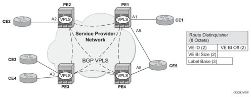
Figure 81 shows the service representation for BGP VPLS mesh. The major BGP VPLS components and the deltas from LDP VPLS with BGP AD are as follows:
- Data plane is identical with the LDP VPLS solution; for example, VPLS instances interconnected by pseudowire mesh. Split horizon groups may be used for loop avoidance between pseudowires.
- Addressing is based on a 2-byte VE-ID assigned to the VPLS instance.
- BGP-AD for LDP VPLS: 4-byte VSI-ID (system IP) identifies the VPLS instance.
- The target VPLS instance is identified by the Route Target (RT) contained in the MP-BGP advertisement (extended community attribute).
- BGP-AD: a new MP-BGP extended community is used to identify the VPLS. RT is used for topology control.
- Auto-discovery is MP-BGP based; the same AFI, SAFI is used as for LDP VPLS BGP-AD.
- The BGP VPLS updates are distinguished from the BGP-AD updates based on the value of the NLRI prefix length: 17 bytes for BGP VPLS, 12 bytes for BGP-AD.
- BGP-AD NLRI is shorter since there is no need to carry pseudowire label information as T-LDP does the pseudowire signaling for LDP VPLS.
- Pseudowire label signaling is MP-BGP based. Therefore, the BGP NLRI content also includes label-related information; for example, block offset, block size, and label base.
- LDP VPLS: target LDP (T-LDP) is used for signaling the pseudowire service label.
- The Layer 2 extended community proposed in RFC 4761 is used to signal pseudowire characteristics; for example, VPLS status, control word, and sequencing.
3.2.17.1. Pseudowire Signaling Details
The pseudowire is set up using the following NLRI fields:
- VE Block offset (VBO): used to define each VE-ID set for which the NLRI is targeted:
- VBO = n*VBS+1; for VBS = 8, this results in 1, 9, 17, 25, …
- Targeted Remote VE-IDs are from VBO to (VBO + VBS − 1)
- VE Block size (VBS): defines how many contiguous pseudowire labels are reserved, starting with the Label Base:
- Nokia implementation always uses a value of eight (8).
- Label Base (LB): local allocated label base:
- The next eight consecutive labels available are allocated for remote PEs.
This BGP update is telling the other PEs that accept the RT: reach me (VE-ID = x), use a pseudowire label of LB + VE-ID – VBO using the BGP NLRI for which VBO =< local VE-ID < VBO + VBS.
Following is an example of how this algorithm works, assuming PE1 has VE-ID 7 configured:
- PE1 allocates a label block of eight consecutive labels available, starting with LB = 1000.
- PE1 starts sending a BGP update with pseudowire information of VBO = 1, VBS = 8, LB = 1000 in the NLRI.
- This pseudowire information will be accepted by all participating PEs with VE-IDs from 1 to 8.
- Each of the receiving PEs will use the pseudowire label = LB + VE-ID − VBO to send traffic back to the originator PE. For example, VE-ID 2 will use pseudowire label 1001.
Assuming that VE-ID = 10 is configured in another PE4, the following procedure applies:
- PE4 sends a BGP update with the new VE-ID in the network that will be received by all the other participating PEs, including PE1.
- Upon reception, PE1 will generate another label block of 8 labels for the VBO = 9. For example, the initial PE will create new pseudowire signaling information of VBO = 9, VBS = 8, LB = 3000, and insert it in a new NLRI and BGP update that is sent in the network.
- This new NLRI will be used by the VE-IDs from 9 to 16 to establish pseudowires back to the originator PE1. For example, PE4 with VE-ID 10 will use pseudowire label 3001 to send VPLS traffic back to PE1.
- The PEs owning the set of VE-IDs from 1 to 8 will ignore this NLRI.
In addition to the pseudowire label information, the Layer2 Info Extended Community attribute must be included in the BGP update for BGP VPLS to signal the attributes of all the pseudowires that converge toward the originator VPLS PE.
The format is as follows:
The meaning of the fields are as follows:
- Extended community type – the value allocated by IANA for this attribute is 0x800A
- Encaps Type – Encapsulation type; identifies the type of pseudowire encapsulation. The only value used by BGP VPLS is 19 (13 in HEX). This value identifies the encapsulation to be used for pseudowire instantiated through BGP signaling, which is the same as the one used for Ethernet pseudowire type in regular VPLS. There is no support for an equivalent Ethernet VLAN pseudowire in BGP VPLS in BGP signaling.
- Control Flags – control information regarding the pseudowires (see Figure 81)
- Layer 2 MTU – the Maximum Transmission Unit to be used on the pseudowires
- Reserved – this field is reserved and must be set to zero and ignored on reception except where it is used for VPLS preference.For inter-AS, the preference information must be propagated between autonomous systems. Consequently, as the VPLS preference in a BGP-VPLS or BGP multi-homing update extended community is zero, the local preference is copied by the egress ASBR into the VPLS preference field before sending the update to the eBGP peer. The adjacent ingress ASBR then copies the received VPLS preference into the local preference to prevent the update being considered malformed.
Figure 82 shows the detailed format for the control flags bit vector.
Figure 82: Control Flag Bit Vector Format

The following bits in the control flags are defined as follows:
- S – sequenced delivery of frames that must or must not be used when sending VPLS packets to this PE, depending on whether S is 1 or 0, respectively
- C – a Control word that must or must not be present when sending VPLS packets to this PE, depending on whether C is 1 or 0, respectively. By default, Nokia implementation uses value 0.
- MBZ – Must Be Zero bits, set to zero when sending and ignored when receiving
- D – indicates the status of the whole VPLS instance (VSI); D = 0 if Admin and Operational status are up, D = 1 otherwise
Following are the events that set the D-bit to 1 to indicate VSI down status in the BGP update message sent out from a PE:
- Local VSI is shut down administratively using config service vpls shutdown command.
- All the related endpoints (SAPs or LDP pseudowires) are down.
- There are no related endpoints (SAPs or LDP pseudowires) configured yet in the VSI.
- The intent is to save the core bandwidth by not establishing the BGP pseudowires to an empty VSI.
- Upon reception of a BGP update message with D-bit set to 1, all the receiving VPLS PEs must mark related pseudowires as down.
The following events do not set the D-bit to 1:
- The local VSI is deleted; a BGP update with UNREACH-NLRI is sent out. Upon reception, all remote VPLS PEs must remove the related pseudowires and BGP routes.
- If the local SDP goes down, only the BGP pseudowires mapped to that SDP go down. There is no BGP update sent.
3.2.17.2. Supported VPLS Features
BGP VPLS includes support for a new type of pseudowire signaling based on MP-BGP, based on the existing VPLS instance; therefore, it inherits all the existing Ethernet switching functions.
The use of an automatically created GRE tunnel is enabled by creating the PW template used within the service with the parameter auto-gre-sdp. The GRE SDP and SDP binding is created after a matching BGP route has been received.
Following are some of the most important VPLS features ported to BGP VPLS:
- VPLS data plane features: for example, FDB management, SAPs, LAG access, and BUM rate limiting
- MPLS tunneling: LDP, LDP over RSVP-TE, RSVP-TE, GRE, and MP-BGP based on RFC 3107 (Inter-AS option C solution)
Note: Pre-provisioned SDPs must be configured when RSVP-signaled transport tunnels are used.
- HVPLS topologies, hub and spoke traffic distribution
- Coexists with LDP VPLS (with or without BGP-AD) in the same VPLS instance:
- LDP and BGP-signaling should operate in disjoint domains to simplify loop avoidance.
- Coexists with BGP-based multi-homing
- BGP VPLS is supported as the control plane for B-VPLS
- Supports IGMP/PIM snooping for IPv4
- Support for High Availability is provided
- Ethernet Service OAM toolset is supported: IEEE 802.1ag, Y.1731.
- Not supported OAM features: CPE Ping, MAC trace/ping/populate/purge
- Support for RSVP and LSP P2MP LSP for VPLS/B-VPLS BUM
3.2.18. VCCV BFD Support for VPLS Services
The SR OS supports RFC 5885, which specifies a method for carrying BFD in a pseudowire associated channel. For general information about VCCV BFD, limitations, and configuring, see the VLL Services chapter.
VCCV BFD is supported on the following VPLS services:
- T-LDP spoke-SDP termination on VPLS (including I-VPLS, B-VPLS, and R-VPLS)
- H-VPLS spoke-SDP
- BGP VPLS
- VPLS with BGP auto-discovery
To configure VCCV BFD for H-VPLS (where the pseudowire template does not apply), configure the BFD template using the config>service>vpls>spoke-sdp>bfd-template name command, then enable it using the config>service>vpls>spoke-sdp>bfd-enable command.
For BGP VPLS, a BFD template is referenced from the pseudowire template binding context. To configure VCCV BFD for BGP VPLS, use the config>service>vpls>bgp>pw-template-binding>bfd-template name command and enable it using the config>service>vpls>bgp>pw-template-binding>bfd-enable command.
For BGP-AD VPLS, a BFD template is referenced from the pseudowire template context. To configure VCCV BFD for BGP-AD, use the config>service>vpls>bgp-ad>pw-template-binding>bfd-template name command, and enable it using the config>service>vpls>bgp-ad>pw-template-binding>bfd-enable command.
3.2.19. BGP Multi-Homing for VPLS
This section describes BGP-based procedures for electing a designated forwarder among the set of PEs that are multi-homed to a customer site. Only the local PEs are actively participating in the selection algorithm. The PEs remote from the dual-homed CE are not required to participate in the designated forwarding election for a remote dual-homed CE.
The main components of the BGP-based multi-homing solution for VPLS are:
- Provisioning model
- MP-BGP procedures
- Designated Forwarder Election
- Blackhole avoidance – indicating the designated forwarder change toward the core PEs and access PEs or CEs
- The interaction with pseudowire signaling (BGP/LDP)
Figure 83: BGP Multi-Homing for VPLS
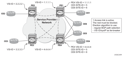
Figure 83 shows the VPLS using BGP multi-homing for the case of multi-homed CEs. Although the figure shows the case of a pseudowire infrastructure signaled with LDP for an LDP VPLS using BGP-AD for discovery, the procedures are identical for BGP VPLS or for a mix of BGP- and LDP-signaled pseudowires.
3.2.19.1. Information Model and Required Extensions to L2VPN NLRI
VPLS Multi-homing using BGP-MP expands on the BGP AD and BGP VPLS provisioning model. The addressing for the multi-homed site is still independent from the addressing for the base VSI (VSI-ID or, respectively, VE-ID). Every multi-homed CE is represented in the VPLS context through a site-ID, which is the same on the local PEs. The site-ID is unique within the scope of a VPLS. It serves to differentiate between the multi-homed CEs connected to the same VPLS Instance (VSI). For example, in Figure 84, CE5 will be assigned the same site-ID on both PE1 and PE4. For the same VPLS instance, different site-IDs are assigned for multi-homed CE5 and CE6; for example, site-ID 5 is assigned for CE5 and site-ID 6 is assigned for CE6. The single-homed CEs (CE1, 2, 3, and 4) do not require allocation of a multi-homed site-ID. They are associated with the addressing for the base VSI, either VSI-ID or VE-ID.
The new information model required changes to the BGP usage of the NLRI for VPLS. The extended MH NLRI for Multi-Homed VPLS is compared with the BGP AD and BGP VPLS NLRIs in Figure 84.
Figure 84: BGP MH-NLRI for VPLS Multi-Homing
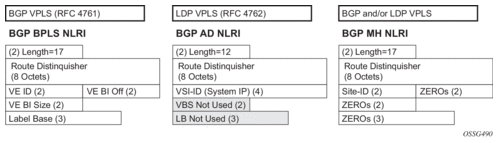
The BGP VPLS NLRI described in RFC 4761 is used to carry a 2-byte site-ID that identifies the MH site. The last seven bytes of the BGP VPLS NLRI used to instantiate the pseudowire are not used for BGP-MH and are zeroed out. This NLRI format translates into the following processing path in the receiving VPLS PE:
- BGP VPLS PE: no label information means there is no need to set up a BGP pseudowire.
- BGP AD for LDP VPLS: length =17 indicates a BGP VPLS NLRI that does not require any pseudowire LDP signaling.
The processing procedures described in this section start from the above identification of the BGP update as not destined for pseudowire signaling.
The RD ensures that the NLRIs associated with a certain site-ID on different PEs are seen as different by any of the intermediate BGP nodes (RRs) on the path between the multi-homed PEs. That is, different RDs must be used on the MH PEs every time an RR or an ASBR is involved to guarantee the MH NLRIs reach the PEs involved in VPLS MH.
The L2-Info extended community from RFC 4761 is used in the BGP update for MH NLRI to initiate a MAC flush for blackhole avoidance, to indicate the operational and admin status for the MH site or the DF election status.
After the pseudowire infrastructure between VSIs is built using either RFC 4762, Virtual Private LAN Service (VPLS) Using Label Distribution Protocol (LDP) Signaling, or RFC 4761 procedures, or a mix of pseudowire signaling procedures, on activation of a multi-homed site, an election algorithm must be run on the local and remote PEs to determine which site will be the designated forwarder (DF). The end result is that all the related MH sites in a VPLS will be placed in standby except for the site selected as DF. Nokia BGP-based multi-homing solution uses the DF election procedure described in the IETF working group document draft-ietf-bess-vpls-multihoming-01. The implementation allows the use of BGP local preference and the received VPLS preference, but does not support setting the VPLS preference to a non-zero value.
3.2.19.2. Supported Services and Multi-Homing Objects
This feature is supported for the following services:
- LDP VPLS with or without BGP-AD
- BGP VPLS (BGP multi-homing for inter-AS BGP-VPLS services is not supported)
- mix of the above
- PBB B-VPLS on BCB
- PBB I-VPLS (see IEEE 802.1ah Provider Backbone Bridging for more information)
The following access objects can be associated with MH Site:
- SAPs
- SDP bindings (pseudowire object), both mesh-SDP and spoke-SDP
- Split Horizon Group
- Under the SHG we can associate either one or multiple of the following objects: SAPs, pseudowires (BGP VPLS, BGP-AD, provisioned and LDP-signaled spoke-SDP and mesh-SDP)
3.2.19.3. Blackhole Avoidance
Blackholing refers to the forwarding of frames to a PE that is no longer carrying the designated forwarder. This could happen for traffic from:
- Core PE participating in the main VPLS
- Customer Edge devices (CEs)
- Access PEs – pseudowires between them and the MH PEs are associated with MH sites
Changes in DF election results or MH site status must be detected by all of the above network elements to provide for Blackhole Avoidance.
3.2.19.3.1. MAC Flush to the Core PEs
Assuming that there is a transition of the existing DF to non-DF status, the PE that owns the MH site experiencing this transition will generate a MAC flush-all-from-me (negative MAC flush) toward the related core PEs. Upon reception, the remote PEs will flush all the MACs learned from the MH PE.
MAC flush-all-from-me indication message is sent using the following core mechanisms:
- For LDP VPLS running between core PEs, existing LDP MAC flush will be used.
- For pseudowire signaled with BGP VPLS, MAC flush will be provided implicitly using the L2-Info Extended community to indicate a transition of the active MH site; for example, the attached objects going down or more generically, the entire site going from Designated Forwarder (DF) to non-DF.
- Double flushing will not happen as it is expected that between any pair of PEs there will exist only one type of pseudowires – either BGP or LDP pseudowire, but not both.
3.2.19.3.2. Indicating non-DF status toward the access PE or CE
For the CEs or access PEs, support is provided for indicating the blocking of the MH site using the following procedures:
- For MH Access PE running LDP pseudowires, the LDP standby-status is sent to all LDP pseudowires.
- For MH CEs, site deactivation is linked to a CCM failure on a SAP that has a down MEP configured.
3.2.19.4. BGP Multi-Homing for VPLS Inter-Domain Resiliency
BGP MH for VPLS can be used to provide resiliency between different VPLS domains. An example of a multi-homing topology is shown in Figure 85.
Figure 85: BGP MH Used in an HVPLS Topology
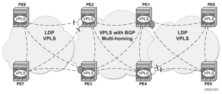
LDP VPLS domains are interconnected using a core VPLS domain, either BGP VPLS or LDP VPLS. The gateway PEs, for example PE2 and PE3, are running BGP multi-homing where one MH site is assigned to each of the pseudowires connecting the access PE, PE7, and PE8 in this example.
Alternatively, the MH site can be associated with multiple access pseudowires using an access SHG. The config>service>vpls>site>failed-threshold command can be used to indicate the number of pseudowire failures that are required for the MH site to be declared down.
3.2.20. Multicast-Aware VPLS
VPLS is a Layer 2 service; therefore, multicast and broadcast frames are normally flooded in a VPLS. Broadcast frames are targeted to all receivers. However, for IP multicast, normally for a multicast group, only some receivers in the VPLS are interested. Flooding to all sites can cause wasted network bandwidth and unnecessary replication on the ingress PE router.
To avoid this condition, VPLS is IP multicast-aware; therefore, it forwards IP multicast traffic based on multicast states to the object on which the IP multicast traffic is requested. This is achieved by enabling the following related IP multicast protocol snooping:
- IGMP snooping
- MLD snooping
- PIM snooping
3.2.20.1. IGMP Snooping for VPLS
When IGMP snooping is enabled in a VPLS service, IGMP messages received on SAPs and SDPs are snooped in order to determine the scope of the flooding for a specified stream or (S,G). IGMP snooping operates in a proxy mode, where the system summarizes upstream IGMP reports and responds to downstream queries. See “IGMP Snooping” in the 7450 ESS, 7750 SR, and VSR Triple Play Service Delivery Architecture Guide for a description of IGMP snooping.
Streams are sent to all SAPs/SDPs on which there is a multicast router (either discovered dynamically from received query messages or configured statically using the mrouter-port command) and on which an active join for that stream has been received. The mrouter port configuration adds a (*,*) entry into the MFIB, which causes all groups (and IGMP messages) to be sent out of the respective object and causes IGMP messages received on that object to be discarded.
Directly connected multicast sources are supported when IGMP snooping is enabled.
IGMP snooping is enabled at the service level and is not supported in the following services:
- B-VPLS
- Routed I-VPLS
- PBB B-VPLS services
IGMP snooping is not supported on a router configured with enable-inter-as-vpn or enable-rr-vpn-forwarding.
IGMP snooping is not supported under the following forms of default SAP:
- *
- *.null
- *.*
IGMP snooping is not supported in a VPLS service configured with a connection profile VLAN SAP.
3.2.20.2. MLD Snooping for VPLS
MLD snooping is an IPv6 version of IGMP snooping. The guidelines and procedures are similar to IGMP snooping as previously described. However, MLD snooping uses MAC-based forwarding. See MAC-Based IPv6 Multicast Forwarding for more information. Directly connected multicast sources are supported when MLD snooping is enabled.
MLD snooping is enabled at the service level and is not supported in the following services:
- B-VPLS
- Routed I-VPLS
- EVPN-MPLS services
- PBB-EVPN services
MLD snooping is not supported under the following forms of default SAP:
- *
- *.null
- *.*
MLD snooping is not supported in a VPLS service configured with a connection profile VLAN SAP.
3.2.20.3. PIM Snooping for VPLS
PIM snooping for VPLS allows a VPLS PE router to build multicast states by snooping PIM protocol packets that are sent over the VPLS. The VPLS PE then forwards multicast traffic based on the multicast states. When all receivers in a VPLS are IP multicast routers running PIM, multicast forwarding in the VPLS is efficient when PIM snooping for VPLS is enabled.
Because of PIM join/prune suppression, in order to make PIM snooping operate over VPLS pseudowires, two options are available: plain PIM snooping and PIM proxy. PIM proxy is the default behavior when PIM snooping is enabled for a VPLS.
PIM snooping is supported for both IPv4 and IPv6 multicast by default and can be configured to use SG-based forwarding (see IPv6 Multicast Forwarding for more information).
Directly connected multicast sources are supported when PIM snooping is enabled.
The following restrictions apply to PIM snooping:
- PIM snooping for IPv4 and IPv6 is not supported:
- in the following services:
- PBB B-VPLS
- R-VPLS (including I-VPLS and BGP EVPN)
- PBB-EVPN B-VPLS
- EVPN-VXLAN R-VPLS
- on a router configured with enable-inter-as-vpn or enable-rr-vpn-forwarding
- under the following forms of default SAP:
- *
- *.null
- *.*
- in a VPLS service configured with a connection profile VLAN SAP
- with connected SR OSs configured with improved-assert
- with subscriber management in the VPLS service
- as a mechanism to drive MCAC
- PIM snooping for IPv6 is not supported:
- in the following services:
- PBB I-VPLS
- BGP-VPLS
- BGP EVPN (including PBB-EVPN)
- VPLS E-Tree
- Management VPLS
- with the configuration of MLD snooping
3.2.20.3.1. Plain PIM Snooping
In a plain PIM snooping configuration, VPLS PE routers only snoop; PIM messages are generated on their own. Join/prune suppression must be disabled on CE routers.
When plain PIM snooping is configured, if a VPLS PE router detects a condition where join/prune suppression is not disabled on one or more CE routers, the PE router will put PIM snooping into the PIM proxy state. A trap is generated that reports the condition to the operator and is logged to the syslog. If the condition changes, for example, join/prune suppression is disabled on CE routers, the PE reverts to the plain PIM snooping state. A trap is generated and is logged to the syslog.
3.2.20.3.2. PIM Proxy
For PIM proxy configurations, VPLS PE routers perform the following:
- snoop hellos and flood hellos in the fast data path
- consume join/prune messages from CE routers
- generate join/prune messages upstream using the IP address of one of the downstream CE routers
- run an upstream PIM state machine to determine whether a join/prune message should be sent upstream
Join/prune suppression is not required to be disabled on CE routers, but it requires all PEs in the VPLS to have PIM proxy enabled. Otherwise, CEs behind the PEs that do not have PIM proxy enabled may not be able to get multicast traffic that they are interested in if they have join/prune suppression enabled.
When PIM proxy is enabled, if a VPLS PE router detects a condition where join/prune suppression is disabled on all CE routers, the PE router puts PIM proxy into a plain PIM snooping state to improve efficiency. A trap is generated to report the scenario to the operator and is logged to the syslog. If the condition changes, for example, join/prune suppression is enabled on a CE router, PIM proxy is placed back into the operational state. Again, a trap is generated to report the condition to the operator and is logged to the syslog.
3.2.20.4. IPv6 Multicast Forwarding
When MLD snooping or PIM snooping for IPv6 is enabled, the forwarding of IPv6 multicast traffic is MAC-based; see MAC-Based IPv6 Multicast Forwarding for more information.
The operation with PIM snooping for IPv6 can be changed to SG-based forwarding; see SG-Based IPv6 Multicast Forwarding for more information.
The following command configures the IPv6 multicast forwarding mode with the default being mac-based:
The forwarding mode can only be changed when PIM snooping for IPv6 is disabled.
3.2.20.4.1. MAC-Based IPv6 Multicast Forwarding
This section describes IPv6 multicast address to MAC address mapping and IPv6 multicast forwarding entries.
For IPv6 multicast address to MAC address mapping, Ethernet MAC addresses in the range of 33-33-00-00-00-00 to 33-33-FF-FF-FF-FF are reserved for IPv6 multicast. To map an IPv6 multicast address to a MAC-layer multicast address, the low-order 32 bits of the IPv6 multicast address are mapped directly to the low-order 32 bits in the MAC-layer multicast address.
For IPv6 multicast forwarding entries, IPv6 multicast snooping forwarding entries are based on MAC addresses, while native IPv6 multicast forwarding entries are based on IPv6 addresses. When both MLD snooping or PIM snooping for IPv6 and native IPv6 multicast are enabled on the same device, both types of forwarding entries are supported on the same forward plane, although they are used for different services.
The following output shows a service with PIM snooping for IPv6 that has received joins for two multicast groups from different sources. As the forwarding mode is MAC-based, there is a single MFIB entry created to forward these two groups.
3.2.20.4.2. SG-Based IPv6 Multicast Forwarding
When PIM snooping for IPv6 is configured, SG-based forwarding can be enabled, which causes the IPv6 multicast forwarding to be based on both the source (if specified) and destination IPv6 address in the received join.
Enabling SG-based forwarding increases the MFIB usage if the source IPv6 address or higher 96 bits of the destination IPv6 address varies in the received joins compared to using MAC-based forwarding.
The following output shows a service with PIM snooping for IPv6 that has received joins for two multicast groups from different sources. As the forwarding mode is SG-based, there are two MFIB entries, one for each of the two groups.
SG-based IPv6 multicast forwarding is supported when both plain PIM snooping and PIM proxy are supported.
SG-based forwarding is only supported on FP3- or higher-based line cards. It is supported in all services in which PIM snooping for IPv6 is supported, with the same restrictions.
It is not supported in the following services:
- PBB B-VPLS
- PBB I-VPLS
- Routed-VPLS (including with I-VPLS and BGP-EVPN)
- BGP-EVPN-MPLS (including PBB-EVPN)
- VPLS E-Tree
- Management VPLS
In any specific service, SG-based forwarding and MLD snooping are mutually exclusive. Consequently, MLD snooping uses MAC-based forwarding.
It is not supported in services with:
- subscriber management
- multicast VLAN Registration
- video interface
It is not supported on connected SR OS routers configured with improved-assert.
It is not supported with the following forms of default SAP:
- *
- *.null
- *.*
3.2.20.5. PIM and IGMP/MLD Snooping Interaction
When both PIM snooping for IPv4 and IGMP snooping are enabled in the same VPLS service, multicast traffic is forwarded based on the combined multicast forwarding table. When PIM snooping is enabled, IGMP queries are forwarded but not snooped, consequently the IGMP querier needs to be seen either as a PIM neighbor in the VPLS service or the SAP towards it configured as an IGMP mrouter port.
There is no interaction between PIM snooping for IPv6 and PIM snooping for IPv4/IGMP snooping when all are enabled within the same VPLS service. The configurations of PIM snooping for IPv6 and MLD snooping are mutually exclusive.
When PIM snooping is enabled within a VPLS service, all IP multicast traffic and flooded PIM messages (these include all PIM snooped messages when not in PIM proxy mode and PIM hellos when in PIM proxy mode) will be sent to any SAP or SDP binding configured with an IGMP-snooping mrouter port. This will occur even without IGMP-snooping enabled, but is not supported in a BGP-VPLS or M-VPLS service.
3.2.20.6. Multi-Chassis Synchronization for Layer 2 Snooping States
To achieve a faster failover in scenarios with redundant active/standby routers performing Layer 2 multicast snooping, it is possible to synchronize the snooping state from the active router to the standby router, so that if a failure occurs the standby router has the Layer 2 multicast snooped states and is able to forward the multicast traffic immediately. Without this capability, there would be a longer delay in re-establishing the multicast traffic path due to having to wait for the Layer 2 states to be snooped.
Multi-chassis synchronization (MCS) is enabled per peer router and uses a sync-tag, which is configured on the objects requiring synchronization on both of the routers. This allows MCS to map the state of a set of objects on one router to a set of objects on the other router. Specifically, objects relating to a sync-tag on one router are backed up by, or are backing up, the objects using the same sync-tag on the other router (the state is synchronized from the active object on one router to its backup objects on the standby router).
The object type must be the same on both routers; otherwise, a mismatch error is reported. The same sync-tag value can be reused for multiple peer/object combinations, where each combination represents a different set of synchronized objects; however, a sync-tag cannot be configured on the same object to more than one peer.
The sync-tag is configured per port and can relate to a specific set of dot1q or QinQ VLANs on that port, as follows.
For IGMP snooping and PIM snooping for IPv4 to work correctly with MCS on QinQ ports using x.* SAPs, one of the following must be true:
- MCS is configured with a sync-tag for the entire port.
- The IGMP snooping SAP and the MCS sync-tag must be provisioned with the same Q-tag values when using the range parameter.
3.2.20.6.1. IGMP Snooping Synchronization
MCS for IGMP snooping synchronizes the join/prune state information from IGMP messages received on the related port/VLANs corresponding to their associated sync-tag. It is enabled as follows.
IGMP snooping synchronization is supported wherever IGMP snooping is supported (except in EVPN for VXLAN). See IGMP Snooping for VPLS for more information. IGMP snooping synchronization is also only supported for the following active/standby redundancy mechanisms:
- MC-LAG
- MC-Ring
- Single-Active Multihoming (EVPN-MPLS and PBB-EVPN I-VPLS)
- Single-Active Multihoming (EVPN-MPLS VPRN and IES routed VPLS)
Configuring an mrouter port under an object that has the synchronization of IGMP snooping states enabled is not recommended. The mrouter port configuration adds a (*,*) entry into the MFIB, which causes all groups (and IGMP messages) to be sent out of the respective object. In addition, the mrouter port command causes all IGMP messages on that object to be discarded. However, the (*,*) entry is not synchronized by MCS. Consequently, the mrouter port could cause the two MCS peers to be forwarding different sets of multicast streams out of the related object when each is active.
3.2.20.6.2. MLD Snooping Synchronization
MCS for MLD snooping is not supported. The command is not blocked for backward-compatibility reasons, but has no effect on the system if configured.
3.2.20.6.3. PIM Snooping for IPv4 Synchronization
MCS for PIM snooping for IPv4 synchronizes the neighbor information from PIM hellos and join/prune state information from PIM for IPv4 messages received on the related SAPs and spoke-SDPs corresponding to the sync-tag associated with the related ports and SDPs, respectively. Use the following CLI syntax to enable MCS for PIM snooping for IPv4 synchronization.
Any PIM hello state information received over the MCS connection from the peer router takes precedence over locally snooped hello information. This ensures that any PIM hello messages received on the active router that are then flooded, for example through the network backbone, and received over a local SAP or SDP on the standby router are not inadvertently used in the standby router’s VPLS service.
The synchronization of PIM snooping state is only supported for manually configured spoke-SDPs. It is not supported for spoke-SDPs configured within an endpoint.
When synchronizing the PIM state between two spoke-SDPs, if both spoke-SDPs go down, the PIM state is maintained on both until one becomes active, in order to ensure that the PIM state is preserved when a spoke-SDP recovers.
Appropriate actions based on the expiration of PIM-related timers on the standby router are only taken after it has become the active peer for the related object (after a failover).
PIM snooping for IPv4 synchronization is supported wherever PIM snooping for IPv4 is supported, excluding the following services:
- BGP-VPLS
- VPLS E-Tree
- management VPLS
See PIM Snooping for VPLS for more details.
PIM snooping for IPv4 synchronization is also only supported for the following active/standby redundancy mechanisms on dual-homed systems:
- MC-LAG
- BGP Multi-homing
- active/standby pseudowires
- Single-Active Multi-homing (EVPN-MPLS and PBB-EVPN I-VPLS)
Configuring an mrouter port under an object that has the synchronization of PIM snooping for IPv4 states enabled is not recommended. The mrouter port configuration adds a (*,*) entry into the MFIB, which causes all groups (and PIM messages) to be sent out of the respective object. In addition, the mrouter port command causes all PIM messages on that object to be discarded. However, the (*,*) entry is not synchronized by MCS. Consequently, the mrouter port could cause the two MCS peers to be forwarding different sets of multicast streams out of the related object when each is active.
3.2.20.7. VPLS Multicast-Aware High Availability Features
The following features are High Availability capable:
- Configuration redundancy — All the VPLS multicast-aware configurations can be synchronized to the standby CPM.
- Local snooping states as well as states distributed by LDP can be synchronized to the standby CPM.
- Operational states can also be synchronized; for example, the operational state of PIM proxy.
3.2.21. RSVP and LDP P2MP LSP for Forwarding VPLS/B-VPLS BUM and IP Multicast Packets
This feature enables the use of a P2MP LSP as the default tree for forwarding Broadcast, Unicast unknown, and Multicast (BUM) packets of a VPLS or B-VPLS instance. The P2MP LSP is referred to in this case as the Inclusive Provider Multicast Service Interface (I-PMSI).
When enabled, this feature relies on BGP Auto-Discovery (BGP-AD) or BGP-VPLS to discover the PE nodes participating in a specified VPLS/B-VPLS instance. The BGP route contains the information required to signal both the point-to-point (P2P) PWs used for forwarding unicast known Ethernet frames and the RSVP P2MP LSP used to forward the BUM frames. The root node signals the P2MP LSP based on an LSP template associated with the I-PMSI at configuration time. The leaf node will automatically join the P2MP LSP that matches the I-PMSI tunnel information discovered via BGP.
If IGMP or PIM snooping are configured on the VPLS instance, multicast packets matching an L2 multicast Forwarding Information Base (FIB) record will also be forwarded over the P2MP LSP.
The user enables the use of an RSVP P2MP LSP as the I-PMSI for forwarding Ethernet BUM and IP multicast packets in a VPLS/B-VPLS instance using the following commands:
config>service>vpls [b-vpls]>provider-tunnel>inclusive>rsvp>lsp-template p2mp-lsp-template-name
The user enables the use of an LDP P2MP LSP as the I-PMSI for forwarding Ethernet BUM and IP multicast packets in a VPLS instance using the following command:
config>service>vpls [b-vpls]>provider-tunnel>inclusive>mldp
After the user performs a no shutdown under the context of the inclusive node and the expiration of a delay timer, BUM packets will be forwarded over an automatically signaled mLDP P2MP LSP or over an automatically signaled instance of the RSVP P2MP LSP specified in the LSP template.
The user can specify that the node is both root and leaf in the VPLS instance:
config>service>vpls [b-vpls]>provider-tunnel>inclusive>root-and-leaf
The root-and-leaf command is required; otherwise, this node will behave as a leaf-only node by default. When the node is leaf only for the I-PMSI of type P2MP RSVP LSP, no PMSI Tunnel Attribute is included in BGP-AD route update messages and, therefore, no RSVP P2MP LSP is signaled, but the node can join an RSVP P2MP LSP rooted at other PE nodes participating in this VPLS/B-VPLS service. The user must still configure a LSP template even if the node is a leaf only. For the I-PMSI of type mLDP, the leaf-only node will join I-PMSI rooted at other nodes it discovered, but will not include a PMSI Tunnel Attribute in BGP route update messages. This way, a leaf-only node will forward packets to other nodes in the VPLS/B-VPLS using the point-to-point spoke-SDPs.
BGP-AD (or BGP-VPLS) must have been enabled in this VPLS/B-VPLS instance or the execution of the no shutdown command under the context of the inclusive node is failed and the I-PMSI will not come up.
Any change to the parameters of the I-PMSI, such as disabling the P2MP LSP type or changing the LSP template, requires that the inclusive node be first shut down. The LSP template is configured in MPLS.
If the P2MP LSP instance goes down, VPLS/B-VPLS immediately reverts the forwarding of BUM packets to the P2P PWs. However, the user can restore at any time the forwarding of BUM packets over the P2P PWs by performing a shutdown under the context of the inclusive node.
This feature is supported with VPLS, H-VPLS, B-VPLS, and BGP-VPLS. It is not supported with I-VPLS and R-VPLS.
3.2.22. MPLS Entropy Label and Hash Label
The router supports the MPLS entropy label (RFC 6790) and the Flow Aware Transport label (known as the hash label) (RFC 6391). These labels allow LSR nodes in a network to load-balance labeled packets in a much more granular fashion than allowed by simply hashing on the standard label stack. See the 7450 ESS, 7750 SR, 7950 XRS, and VSR MPLS Guide for further information.
3.3. Routed VPLS and I-VPLS
This section provides information about Routed VPLS (R-VPLS) and I-VPLS. R-VPLS and I-VPLS apply to the 7450 ESS and 7750 SR.
3.3.1. IES or VPRN IP Interface Binding
For the remainder of this section R-VPLS and Routed I-VPLS will both be described as a VPLS service and differences will be pointed out where applicable.
A standard IP interface within an existing IES or VPRN service context may be bound to a service name. Subscriber and group IP interfaces are not allowed to bind to a VPLS or I-VPLS service context or I-VPLS. A VPLS service only supports binding for a single IP interface.
While an IP interface may only be bound to a single VPLS service, the routing context containing the IP interface (IES or VPRN) may have other IP interfaces bound to other VPLS service contexts of the same type (all VPLS or all I-VPLS). That is, R-VPLS allows the binding of IP interfaces in IES or VPRN services to be bound to VPLS services and Routed I-VPLS allows of IP interfaces in IES or VPRN services to be bound to I-VPLS services.
3.3.1.1. Assigning a Service Name to a VPLS Service
When a service name is applied to any service context, the name and service ID association is registered with the system. A service name cannot be assigned to more than one service ID.
Special consideration is given to a service name that is assigned to a VPLS service that has the config>service>vpls>allow-ip-int-bind command enabled. If a name is applied to the VPLS service while the flag is set, the system will scan the existing IES and VPRN services for an IP interface that is bound to the specified service name. If an IP interface is found, the IP interface will be attached to the VPLS service associated with the name. Only one interface can be bound to the specified name.
If the allow-ip-int-bind command is not enabled on the VPLS service, the system will not attempt to resolve the VPLS service name to an IP interface. As soon as the allow-ip-int-bind flag is configured on the VPLS, the corresponding IP interface will be bound and become operational up. There is no need to toggle the shutdown/no shutdown command.
If an IP interface is not currently bound to the service name used by the VPLS service, no action is taken at the time of the service name assignment.
3.3.1.2. Service Binding Requirements
If the defined service ID is created on the system, the system will check to ensure that the service type is VPLS. If the service type is not VPLS or I-VPLS, service creation will not be allowed and the service ID will remain undefined within the system.
If the created service type is VPLS, the IP interface will be eligible to enter the operationally up state.
3.3.1.3. Bound Service Name Assignment
If a bound service name is assigned to a service within the system, the system will first check to ensure the service type is VPLS or I-VPLS. Secondly, the system will ensure that the service is not already bound to another IP interface via the service ID. If the service type is not VPLS or I-VPLS or the service is already bound to another IP interface via the service ID, the service name assignment will fail.
If a single VPLS service ID and service name is assigned to two separate IP interfaces, the VPLS service will not be allowed to enter the operationally up state.
3.3.1.4. Binding a Service Name to an IP Interface
An IP interface within an IES or VPRN service context may be bound to a service name at any time. Only one interface can be bound to a service.
When an IP interface is bound to a service name and the IP interface is administratively up, the system will scan for a VPLS service context using the name and take the following actions:
- If the name is not currently in use by a service, the IP interface will be placed in an operationally down: Non-existent service name or inappropriate service type state.
- If the name is currently in use by a non-VPLS service or the wrong type of VPLS service, the IP interface will be placed in the operationally down: Non-existent service name or inappropriate service type state.
- If the name is currently in use by a VPLS service without the allow-ip-int-bind flag set, the IP interface will be placed in the operationally down: VPLS service allow-ip-int-bind flag not set state. There is no need to toggle the shutdown/no shutdown command.
- If the name is currently in use by a valid VPLS service and the allow-ip-int-bind flag is set, the IP interface will be eligible to be placed in the operationally up state depending on other operational criteria being met.
3.3.1.5. Bound Service Deletion or Service Name Removal
If a VPLS service is deleted while bound to an IP interface, the IP interface will enter the Down: Non-existent svc-ID operational state. If the IP interface was bound to the VPLS service name, the IP interface will enter the Down: Non-existent svc-name operational state. No console warning is generated.
If the created service type is VPLS, the IP interface will be eligible to enter the operationally up state.
3.3.1.6. IP Interface Attached VPLS Service Constraints
Once a VPLS service has been bound to an IP interface through its service name, the service name assigned to the service cannot be removed or changed unless the IP interface is first unbound from the VPLS service name.
A VPLS service that is currently attached to an IP interface cannot be deleted from the system unless the IP interface is unbound from the VPLS service name.
The allow-ip-int-bind flag within an IP interface attached VPLS service cannot be reset. The IP interface must first be unbound from the VPLS service name to reset the flag.
3.3.1.7. IP Interface and VPLS Operational State Coordination
When the IP interface is successfully attached to a VPLS service, the operational state of the IP interface will be dependent upon the operational state of the VPLS service.
The VPLS service remains down until at least one virtual port (SAP, spoke-SDP, or mesh SDP) is operational.
3.3.2. IP Interface MTU and Fragmentation
The VPLS service is affected by two MTU values: port MTUs and the VPLS service MTU. The MTU on each physical port defines the largest Layer 2 packet (including all DLC headers) that may be transmitted out a port. The VPLS has a service level MTU that defines the largest packet supported by the service. This MTU does not include the local encapsulation overhead for each port (QinQ, Dot1Q, TopQ, or SDP service delineation fields and headers) but does include the remainder of the packet.
As virtual ports are created in the system, the virtual port cannot become operational unless the configured port MTU minus the virtual port service delineation overhead is greater than or equal to the configured VPLS service MTU. Therefore, an operational virtual port is ensured to support the largest packet traversing the VPLS service. The service delineation overhead on each Layer 2 packet is removed before forwarding into a VPLS service. VPLS services do not support fragmentation and must discard any Layer 2 packet larger than the service MTU after the service delineation overhead is removed.
When an IP interface is associated with a VPLS service, the IP-MTU is based on either the administrative value configured for the IP interface or an operational value derived from VPLS service MTU. The operational IP-MTU cannot be greater than the VPLS service MTU minus 14 bytes.
- If the configured (administrative) IP-MTU is configured for a value greater than the normalized IP-MTU, based on the VPLS service-MTU, then the operational IP-MTU is reset to equal the normalized IP-MTU value (VPLS service MTU – 14 bytes).
- If the configured (administrative) IP-MTU is configured for a value less than or equal to the normalized IP-MTU, based on the VPLS service-MTU, then the operational IP-MTU is set to equal the configured (administrative) IP-MTU value.
3.3.2.1. Unicast IP Routing into a VPLS Service
The VPLS service MTU and the IP interface MTU parameters may be changed at any time.
3.3.3. ARP and VPLS FDB Interactions
Two address-oriented table entries are used when routing into a VPLS service. On the routing side, an ARP entry is used to determine the destination MAC address used by an IP next-hop. In the case where the destination IP address in the routed packet is a host on the local subnet represented by the VPLS instance, the destination IP address is used as the next-hop IP address in the ARP cache lookup. If the destination IP address is in a remote subnet that is reached by another router attached to the VPLS service, the routing lookup will return the local IP address on the VPLS service of the remote router. If the next-hop is not currently in the ARP cache, the system will generate an ARP request to determine the destination MAC address associated with the next-hop IP address.
IP routing to all destination hosts associated with the next-hop IP address stops until the ARP cache is populated with an entry for the next-hop. The ARP cache may be populated with a static ARP entry for the next-hop IP address. While dynamically populated ARP entries will age out according to the ARP aging timer, static ARP entries never age out.
The second address table entry that affects VPLS routed packets is the MAC destination lookup in the VPLS service context. The MAC associated with the ARP table entry for the IP next-hop may or may not currently be populated in the VPLS Layer 2 FDB table. While the destination MAC is unknown (not populated in the VPLS FDB), the system will flood all packets destined for that MAC (routed or bridged) to all virtual ports within the VPLS service context. Once the MAC is known (populated in the VPLS FDB), all packets destined for the MAC (routed or bridged) will be targeted to the specific virtual port where the MAC has been learned.
As with ARP entries, static MAC entries may be created in the VPLS FDB. Dynamically learned MAC addresses are allowed to age out or be flushed from the VPLS FDB while static MAC entries always remain associated with a specific virtual port. Dynamic MACs may also be relearned on another VPLS virtual port than the current virtual port in the FDB. In this case, the system will automatically move the MAC FDB entry to the new VPLS virtual port.
The MAC address associated with the R-VPLS IP interface is protected within its VPLS service such that frames received with this MAC address as the source address are discarded. VRRP MAC addresses are not protected in this way.
3.3.3.1. R-VPLS Specific ARP Cache Behavior
In typical routing behavior, the system uses the IP route table to select the egress interface, and then at the egress forwarding engine, an ARP entry is used to forward the packet to the appropriate Ethernet MAC. With R-VPLS, the egress IP interface may be represented by a multiple egress forwarding engine (wherever the VPLS service virtual ports exist).
To optimize routing performance, the ingress forwarding engine processing has been augmented to perform an ingress ARP lookup in order to resolve which VPLS MAC address the IP frame must be routed toward. This MAC address may be currently known or unknown within the VPLS FDB. If the MAC is unknown, the packet is flooded by the ingress forwarding engine to all egress forwarding engines where the VPLS service exists. When the MAC is known on a virtual port, the ingress forwarding engine forwards the packet to the correct egress forwarding engine. Table 34 describes how the ARP cache and MAC FDB entry states interact at ingress and Table 35 describes the corresponding egress behavior.
Table 34: Ingress Routed to VPLS Next-Hop Behavior
Next-Hop ARP Cache Entry | Next-Hop MAC FDB Entry | Ingress Behavior |
ARP Cache Miss (No Entry) | Known or Unknown | Flood to all egress forwarding engines associated with the VPLS or I-VPLS context. |
Unknown | Flood to all egress forwarding engines associated with the VPLS or I-VPLS context. | |
Unknown | Flood to all egress forwarding engines associated with the VPLS for forwarding to all VPLS or I-VPLS virtual ports. |
Table 35: Egress R-VPLS Next-Hop Behavior
Next-Hop ARP Cache Entry | Next-Hop MAC FDB Entry | Egress Behavior |
ARP Cache Miss (No Entry) | Known | No ARP entry. The MAC address is unknown and the ARP request is flooded out of all virtual ports of the VPLS or I-VPLS instance. |
Unknown | Request control engine processing the ARP request to transmit out of all virtual ports associated with the VPLS or I-VPLS service. Only the first egress forwarding engine ARP processing request triggers an egress ARP request. | |
ARP Cache Hit | Known | Forward out of specific egress VPLS or I-VPLS virtual ports where MAC has been learned. |
Unknown | Flood to all egress VPLS or I-VPLS virtual ports on forwarding engine. |
3.3.4. The allow-ip-int-bind VPLS Flag
The allow-ip-int-bind flag on a VPLS service context is used to inform the system that the VPLS service is enabled for routing support. The system uses the setting of the flag as a key to determine the types of ports and forwarding planes the VPLS service may span.
The system also uses the flag state to define which VPLS features are configurable on the VPLS service to prevent enabling a feature that is not supported when routing support is enabled.
3.3.4.1. R-VPLS SAPs Only Supported on Standard Ethernet Ports
The allow-ip-int-bind flag is set (routing support enabled) on a VPLS/I-VPLS service. SAPs within the service can be created on standard Ethernet, HSMDA, and CCAG ports. ATM and POS are not supported.
3.3.4.2. LAG Port Membership Constraints
If a LAG has a non-supported port type as a member, a SAP for the routing-enabled VPLS service cannot be created on the LAG. Once one or more routing enabled VPLS SAPs are associated with a LAG, a non-supported Ethernet port type cannot be added to the LAG membership.
3.3.4.3. R-VPLS Feature Restrictions
When the allow-ip-int-bind flag is set on a VPLS service, the following restrictions apply. The flag also cannot be enabled while any of these features are applied to the VPLS service:
- SAP ingress QoS policies applied to the VPLS SAPs cannot have MAC match criteria defined.
- SDPs used in spoke or mesh SDP bindings cannot be configured as GRE.
- The VPLS service type cannot be B-VPLS or M-VPLS.
- MVR from R-VPLS and to another SAP is not supported.
- Enhanced and Basic Subscriber Management (BSM) features cannot be enabled.
- Network domain on SDP bindings cannot be enabled.
- Per-service hashing is not supported.
- BGP-VPLS is not supported.
- Ingress queuing for split horizon groups is not supported.
- Multiple virtual routers are not supported.
3.3.4.4. Routed I-VPLS Feature Restrictions
The following restrictions apply to routed I-VPLS:
- Multicast is not supported.
- VC-VLANs are not supported on SDPs.
- force-qtag-forwarding is not supported.
- Control words are not supported on B-VPLS SDPs.
- Hash label is not supported on B-VPLS SDPs.
3.3.5. IPv4 and IPv6 Multicast Routing Support
IPv4 and IPv6 multicast routing is supported in a R-VPLS service through its IP interface when the source of the multicast stream is on one side of its IP interface and the receivers are on either side of the IP interface. For example, the source for multicast stream G1 could be on the IP side sending to receivers on both other regular IP interfaces and the VPLS of the R-VPLS service, while the source for group G2 could be on the VPLS side sending to receivers on both the VPLS and IP side of the R-VPLS service.
IPv4 and IPv6 multicast routing is not supported with Multicast VLAN Registration functions or the configuration of a video interface within the associated VPLS service. It is also not supported in a routed I-VPLS service, or for IPv6 multicast in BGP EVPN-MPLS routed VPLS services. Forwarding IPv4 or IPv6 multicast traffic from the R-VPLS IP interface into its VPLS service on a P2MP LSP is not supported.
The IP interface of a R-VPLS supports the configuration of both PIM and IGMP for IPv4 multicast and for both PIM and MLD for IPv6 multicast.
To forward IPv4/IPv6 multicast traffic from the VPLS side of the R-VPLS service to the IP side, the forward-ipv4-multicast-to-ip-int and/or forward-ipv6-multicast-to-ip-int parameters must be configured as follows:
Enabling IGMP snooping or MLD snooping in the VPLS service is optional, where supported. If IGMP/MLD snooping is enabled, IGMP/MLD must be enabled on the R-VPLS IP interface in order for multicast traffic to be sent into, or received from, the VPLS service. IPv6 multicast uses MAC-based forwarding; see MAC-Based IPv6 Multicast Forwarding for more information.
If both IGMP/MLD and PIM for IPv4/IPv6 are configured on the R-VPLS IP interface in a redundant PE topology, the associated IP interface on one of the PEs must be configured as both the PIM designated router and the IGMP/MLD querier. This ensures that the multicast traffic is sent into the VPLS service, as IGMP/MLD joins are only propagated to the IP interface if it is the IGMP/MLD querier. An alternative to this is to configure the R-VPLS IP interface in the VPLS service as an mrouter port, as follows:
This configuration achieves a faster failover in scenarios with redundant routers where multicast traffic is sent to systems on the VPLS side of their R-VPLS services and IGMP/MLD snooping is enabled in the VPLS service. If the active router fails, the remaining router does not have to wait until it sends an IGMP/MLD query into the VPLS service before it starts receiving IGMP/MLD joins, and starts sending the multicast traffic into the VPLS service. When the mrouter port is configured as above, all IGMP/MLD joins (and multicast traffic) are sent to the VPLS service IP interface.
IGMP/MLD snooping should only be enabled when systems, as opposed to PIM routers, are connected to the VPLS service. If IGMP/MLD snooping is enabled when the VPLS service is used for transit traffic for connected PIM routers, the IGMP/MLD snooping would prevent multicast traffic being forwarded between the PIM routers (as PIM snooping is not supported). A workaround would be to configure the VPLS SAPs and spoke-SDPs (and the R-VPLS IP interface) to which the PIM routers are connected as mrouter ports.
If IMPM is enabled on an FP on which there is a R-VPLS service with forward-ipv4-multicast-to-ip-int or forward-ipv6-multicast-to-ip-int configured, the IPv4/IPv6 multicast traffic received in the VPLS service that is forwarded through the IP interface will be IMPM-managed even without IGMP/MLD snooping being enabled. This does not apply to traffic that is only flooded within the VPLS service.
When IPv4/IPv6 multicast traffic is forwarded from a VPLS SAP through the R-VPLS IP interface, the packet count is doubled in the following statistics to represent both the VPLS and IP replication (this reflects the capacity used for this traffic on the ingress queues, which is subject to any configured rates and IMPM capacity management):
- Offered queue statistics
- IMPM managed statistics
- IMPM unmanaged statistics for policed traffic
IPv4 or IPv6 multicast traffic entering the IP side of the R-VPLS service and exiting over a multi-port LAG on the VPLS side of the service is sent on a single link of that egress LAG, specifically the link used for all broadcast, unknown, and multicast traffic.
An example of IPv4/IPv6 multicast in a R-VPLS service is shown in Figure 86. There are two R-VPLS IP interfaces connected to an IES service with the upper interface connected to a VPLS service in which there is a PIM router and the lower interface connected to a VPLS service in which there is a system using IGMP/MLD.
Figure 86: IPv4/IPv6 Multicast with a Router VPLS Service
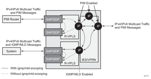
The IPv4/IPv6 multicast traffic entering the IES/VPRN service through the regular IP interface is replicated to both the other regular IP interface and the two R-VPLS interfaces if PIM/IGMP/MLD joins have been received on the respective IP interfaces. This traffic will be flooded into both VPLS services unless IGMP/MLD snooping is enabled in the lower VPLS service, in which case it is only sent to the system originating the IGMP/MLD join.
The IPv4/IPv6 multicast traffic entering the upper VPLS service from the connected PIM router will be flooded in that VPLS service and, if related joins have been received, forwarded to the regular IP interfaces in the IES/VPRN. It will also be forwarded to the lower VPLS service if an IGMP/MLD join is received on its IP interface, and will be flooded in that VPLS service unless IGMP/MLD snooping is enabled.
The IPv4/IPv6 multicast traffic entering the lower VPLS service from the connected system will be flooded in that VPLS service, unless IGMP/MLD snooping is enabled, in which case it will only be forwarded to SAPs, spoke-SDPs, or the R-VPLS IP interface if joins have been received on them. It will be forwarded to the regular IP interfaces in the IES/VPRN service if related joins have been received on those interfaces, and it will also be forwarded to the upper VPLS service if a PIM IPv4/IPv6 join is received on its IP interface, this being flooded in that VPLS service.
3.3.6. BGP Auto-Discovery (BGP-AD) for R-VPLS Support
BGP Auto-Discovery (BGP-AD) for R-VPLS is supported. BGP-AD for LDP VPLS is an already supported framework for automatically discovering the endpoints of a Layer 2 VPN offering an operational model similar to that of an IP VPN.
3.3.7. R-VPLS Caveats
3.3.7.1. VPLS SAP Ingress IP Filter Override
When an IP Interface is attached to a VPLS or an I-VPLS service context, the VPLS SAP provisioned IP filter for ingress routed packets may be optionally overridden in order to provide special ingress filtering for routed packets. This allows different filtering for routed packets and non-routed packets. The filter override is defined on the IP interface bound to the VPLS service name. A separate override filter may be specified for IPv4 and IPv6 packet types.
If a filter for a specified packet type (IPv4 or IPv6) is not overridden, the SAP specified filter is applied to the packet (if defined).
3.3.7.2. IP Interface Defined Egress QoS Reclassification
The SAP egress QoS policy defined forwarding class and profile reclassification rules are not applied to egress routed packets. To allow for egress reclassification, a SAP egress QoS policy ID may be optionally defined on the IP interface that will be applied to routed packets that egress the SAPs on the VPLS or I-VPLS service associated with the IP interface. Both unicast directed and MAC unknown flooded traffic apply to this rule. Only the reclassification portion of the QoS policy is applied, which includes IP precedence or DSCP classification rules and any defined IP match criteria and their associated actions.
The policers and queues defined within the QoS policy applied to the IP interface are not created on the egress SAPs of the VPLS service. Instead, the QoS policy applied to the egress SAPs defines the egress policers and queues that will be used by both routed and non-routed egress packets. The forwarding class mappings defined in the egress SAP’s QoS policy will also define which policer or queue will handle each forwarding class for both routed and non-routed packets.
3.3.7.3. Remarking for VPLS and Routed Packets
The remarking of packets to and from an IP interface in an R-VPLS service corresponds to that supported on IP interface, even though the packets ingress or egress a SAP in the VPLS service bound to the IP service. Specifically, this results in the ability to remark the DSCP/prec for these packets.
Packets ingressing and egressing SAPs in the VPLS service (not routed through the IP interface) support the regular VPLS QoS and, therefore, the DSCP/prec cannot be remarked.
3.3.7.4. 7450 Mixed Mode Chassis
The mixed mode on the 7450 ESS that allows 7750 SR-based IOMs to be populated and operational in a 7450 ESS chassis supports R-VPLS as long as all the forwarding plane and port type restrictions are observed.
3.3.7.5. IPv4 Multicast Routing
When using IPv4 Multicast routing, the following are not supported:
- multicast VLAN registration functions within the associated VPLS service
- configuration of a video ISA within the associated VPLS service
- configuration of MFIB-allowed MDA destinations under spoke/mesh SDPs within the associated VPLS service
- IPv4 multicast routing is not supported in Routed I-VPLS.
- RFC 6037 multicast tunnel termination (including when the system is a bud node) is not supported on the R-VPLS IP interface for multicast traffic received in the VPLS service.
- Forwarding of multicast traffic from the VPLS side of the service to the IP interface side of the service is not supported for R-VPLS services in which VXLAN is enabled.
3.3.7.6. R-VPLS Supported Routing-related Protocols
The following protocols are supported on IP interfaces bound to a VPLS service:
- BGP
- OSPF
- ISIS
- PIM
- IGMP
- BFD
- VRRP
- ARP
- DHCP Relay
3.3.7.7. Spanning Tree and Split Horizon
A R-VPLS context supports all spanning tree and split horizon capabilities that a non-R-VPLS service supports.
3.4. VPLS Service Considerations
This section describes the 7450 ESS, 7750 SR, and 7950 XRS service features and any special capabilities or considerations as they relate to VPLS services.
3.4.1. SAP Encapsulations
VPLS services are designed to carry Ethernet frame payloads, so the services can provide connectivity between any SAPs and SDPs that pass Ethernet frames. The following SAP encapsulations are supported on the 7450 ESS, 7750 SR, and 7950 XRS VPLS services:
- Ethernet null
- Ethernet dot1q
- Ethernet QinQ
- SONET/SDH BCP-null
- SONET/SDH BCP-dot1q
- ATM VC with RFC 2684 Ethernet bridged encapsulation (See ATM/Frame Relay PVC Access and Termination on a VPLS Service.)
- FR VC with RFC 2427 Ethernet bridged encapsulation (See ATM/Frame Relay PVC Access and Termination on a VPLS Service.)
3.4.2. VLAN Processing
The SAP encapsulation definition on Ethernet ingress ports defines which VLAN tags are used to determine the service to which the packet belongs:
- Null encapsulation defined on ingress — Any VLAN tags are ignored and the packet goes to a default service for the SAP.
- Dot1q encapsulation defined on ingress — Only first label is considered.
- QinQ encapsulation defined on ingress— Both labels are considered. The SAP can be defined with a wildcard for the inner label (for example, “100:100.*”). In this situation, all packets with an outer label of 100 will be treated as belonging to the SAP. If, on the same physical link, there is also a SAP defined with a QinQ encapsulation of 100:100.1, then traffic with 100:1 will go to that SAP and all other traffic with 100 as the first label will go to the SAP with the 100:100.* definition.
In situations 2 and 3 above, traffic encapsulated with tags for which there is no definition are discarded.
3.4.3. Ingress VLAN Swapping
This feature is supported on VPLS and VLL service where the end-to-end solution is built using two node solutions (requiring SDP connections between the nodes).
In VLAN swapping, only the VLAN ID value will be copied to the inner VLAN position. Ethertype of the inner tag will be preserved and all consecutive nodes will work with that value. Similarly, the dot1p bits value of outer tag will not be preserved.
Figure 87: Ingress VLAN Swapping
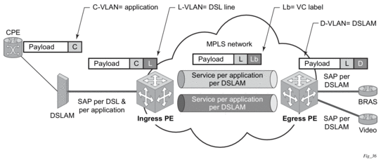
Figure 87 describes the network where, at user access side (DSLAM facing SAPs), every subscriber is represented by several QinQ SAPs with inner-tag encoding service and outer-tag encoding subscriber (DSL line). The aggregation side (BRAS or PE-facing SAPs) is represented by a DSL line number (inner VLAN tag) and DSLAM (outer VLAN tag). The effective operation on the VLAN tag is to drop the inner tag at the access side and push another tag at the aggregation side.
3.4.4. Service Auto-Discovery using Multiple VLAN Registration Protocol (MVRP)
IEEE 802.1ak Multiple VLAN Registration Protocol (MVRP) is used to advertise throughout a native Ethernet switching domain one or multiple VLAN IDs to automatically build native Ethernet connectivity for multiple services. These VLAN IDs can be either Customer VLAN IDs (CVID) in an enterprise switching environment, Stacked VLAN IDs (SVID) in a Provider Bridging, QinQ Domain (refer to IEEE 802.1ad), or Backbone VLAN IDs (BVID) in a Provider Backbone Bridging (PBB) domain (refer to IEEE 802.1ah).
The initial focus of Nokia MVRP implementation is a Service Provider QinQ domain with or without a PBB core. The QinQ access into a PBB core example is used throughout this section to describe the MVRP implementation. With the exception of end-station components, a similar solution can be used to address a QinQ only or enterprise environments.
The components involved in the MVRP control plane are shown in Figure 88.
Figure 88: Infrastructure for MVRP Exchanges
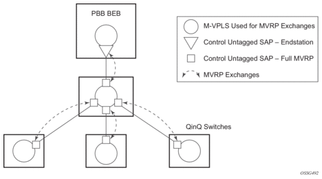
All the devices involved are QinQ switches with the exception of the PBB BEB which delimits the QinQ domain and ensures the transition to the PBB core. The circles represent Management VPLS instances interconnected by SAPs to build a native Ethernet switching domain used for MVRP control plane exchanges.
The following high-level steps are involved in auto-discovery of VLAN connectivity in a native Ethernet domain using MVRP:
- Configure the MVRP infrastructure
- This requires the configuration of a Management VPLS (M-VPLS) context.
- MSTP may be used in M-VPLS to provide the loop-free topology over which the MVRP exchanges take place.
- Instantiate related VLAN FDB, trunks in the MVRP, M-VPLS scope
- The VLAN FDBs (VPLS instances) and associated trunks (SAPs) are instantiated in the same Ethernet switches and on the same “trunk ports” as the M-VPLS.
- There is no need to instantiate data VPLS instances in the BEB. I-VPLS instances and related downward-facing SAPs will be provisioned manually because the ISID-to-VLAN association must be configured.
- MVRP activation of service connectivity
- When the first two customer UNI and/or PBB end-station SAPs are configured on different Ethernet switches in a certain service context, the MVRP exchanges will activate service connectivity.
3.4.4.1. Configure the MVRP Infrastructure using an M-VPLS Context
The following provisioning steps apply:
- Configure M-VPLS instances in the switches that will participate in MVRP control plane
- Configure under the M-VPLS the untagged SAPs to be used for MVRP exchanges; only dot1q or qinq ports are accepted for MVRP enabled M-VPLS
- Configure MVRP parameters at M-VPLS instance or SAP level
3.4.4.2. Instantiate Related VLAN FDBs and Trunks in MVRP Scope
This requires the configuration in the M-VPLS, under vpls-group, of the following attributes: VLAN ranges, vpls-template and vpls-sap-template bindings. As soon as the VPLS group is enabled, the configured attributes are used to auto-instantiate, on a per-VLAN basis, a VPLS FDB and related SAPs in the switches and on the “trunk ports” specified in the M-VPLS context. The trunk ports are ports associated with an M-VPLS SAP not configured as an end-station.
The following procedure is used:
- The vpls-template binding is used to instantiate the VPLS instance where the service ID is derived from the VLAN value as per service-range configuration.
- The vpls-sap-template binding is used to create dot1q SAPs by deriving from the VLAN value the service delimiter as per service-range configuration.
The above procedure may be used outside of the MVRP context to pre-provision a large number of VPLS contexts that share the same infrastructure and attributes.
The MVRP control of the auto-instantiated services can be enabled using the mvrp-contrl command under vpls-group:
- If mvrp-control is disabled, the auto-created VPLS instances and related SAPs are ready to forward.
- If mvrp-control is enabled, the auto-created VPLS instances will be instantiated initially with an empty flooding domain. The MVRP exchanges will gradually enable service connectivity according to the operator configuration – between configured SAPs in the data VPLS context.
- This also provides protection against operational mistakes that may generate flooding throughout the auto-instantiated VLAN FDBs.
From an MVRP perspective, these SAPs can be either “full MVRP” or “end-station” interfaces.
A full MVRP interface is a full participant in the local M-VPLS scope:
- VLAN attributes received in an MVRP registration on this MVRP interface are declared on all the other full MVRP SAPs in the control VPLS.
- VLAN attributes received in an MVRP registration on other full MVRP interfaces in the local M-VPLS context are declared on this MVRP interface.
In an MVRP end-station interface, the attributes registered on that interface have local significance:
- VLAN attributes received in an MVRP registration on this interface are not declared on any other MVRP SAPs in the control VPLS. The attributes are registered only on the local port.
- Only locally active VLAN attributes are declared on the end-station interface; VLAN attributes registered on any other MVRP interfaces are not declared on end-station interfaces.
- Also defining an M-VPLS SAP as an end-station does not instantiate any objects on the local switch; the command is used just to define which SAP needs to be monitored by MVRP to declare the related VLAN value.
The following example describes the M-VPLS configuration required to auto-instantiate the VLAN FDBs and related trunks in non-PBB switches:
A similar M-VPLS configuration may be used to auto-instantiate the VLAN FDBs and related trunks in PBB switches. The vpls-group command is replaced by the end-station command under the downward-facing SAPs as in the following example:
3.4.4.3. MVRP Activation of Service Connectivity
As new Ethernet services are activated, UNI SAPs need to be configured and associated with the VLAN IDs (VPLS instances) auto-created using the procedures described in the previous sections. These UNI SAPs may be located in the same VLAN domain or over a PBB backbone. When UNI SAPs are located in different VLAN domains, an intermediate service translation point must be used at the PBB BEB, which maps the local VLAN ID through an I-VPLS SAP to a PBB ISID. This BEB SAP will be playing the role of an end-station from an MVRP perspective for the local VLAN domain.
This section will discuss how MVRP is used to activate service connectivity between a BEB SAP and a UNI SAP located on one of the switches in the local domain. A similar procedure is used in the case of UNI SAPs configured on two switches located in the same access domain. No end-station configuration is required on the PBB BEB if all the UNI SAPs in a service are located in the same VLAN domain.
The service connectivity instantiation through MVRP is shown in Figure 89.
Figure 89: Service Instantiation with MVRP - QinQ to PBB Example
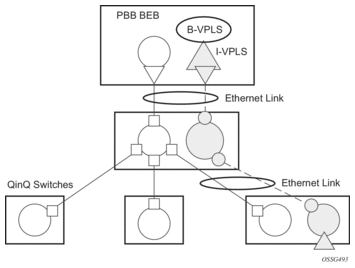
In this example, the UNI and service translation SAPs are configured in the data VPLS represented by the gray circles. This instance and associated trunk SAPs were instantiated using the procedures described in the previous sections. The following configuration steps are involved:
- on the BEB, an I-VPLS SAP must be configured toward the local switching domain – see yellow triangle facing downward
- on the UNI facing the customer, a “customer” SAP is configured on the bottom left switch – see yellow triangle facing upward
As soon as the first UNI SAP becomes active in the data VPLS on the ES, the associated VLAN value is advertised by MVRP throughout the related M-VPLS context. As soon as the second UNI SAP becomes available on a different switch, or in our example on the PBB BEB, the MVRP proceeds to advertise the associated VLAN value throughout the same M-VPLS. The trunks that experience MVRP declaration and registration in both directions will become active, instantiating service connectivity as represented by the big and small yellow circles shown in the figure.
A hold-time parameter (config>service>vpls>mrp>mvrp>hold-time) is provided in the M-VPLS configuration to control when the end-station or last UNI SAP is considered active from an MVRP perspective. The hold-time controls the amount of MVRP advertisements generated on fast transitions of the end-station or UNI SAPs.
If the no hold-time setting is used:
- MVRP will stop declaring the VLAN only when the last provisioned UNI SAP associated locally with the service is deleted.
- MVRP will start declaring the VLAN as soon as the first provisioned SAP is created in the associated VPLS instance, regardless of the operational state of the SAP.
If a non-zero “hold-time” setting is used:
- When a SAP in down state is added, MVRP does not declare the associated VLAN attribute. The attribute is declared immediately when the SAP comes up.
- When the SAP goes down, MVRP will wait until “hold-time” expiry before withdrawing the declaration.
For QinQ end-station SAPs, only no hold-time setting is allowed.
Only the following PBB Epipe and I-VPLS SAP types are eligible to activate MVRP declarations:
- dot1q: for example, 1/1/2:100
- qinq or qinq default: for example, 1/1/1:100.1 and respectively 1/1/1:100.*, respectively; the outer VLAN 100 will be used as MVRP attribute as long as it belongs to the MVRP range configured for the port
- null port and dot1q default cannot be used
Examples of steps required to activate service connectivity for VLAN 100 using MVRP follows.
In the data VPLS instance (VLAN 100) controlled by MVRP, on the QinQ switch:
In I-VPLS on PBB BEB:
3.4.4.4. MVRP Control Plane
MVRP is based on the IEEE 802.1ak MRP specification where STP is the supported method to be used for loop avoidance in a native Ethernet environment. M-VPLS and the associated MSTP (or P-MSTP) control plane provides the loop avoidance component in the Nokia implementation. Nokia MVRP may also be used in a non- MSTP, loop free topology.
3.4.4.5. STP-MVRP Interaction
Table 36 shows the expected interaction between STP (MSTP or P-MSTP) and MVRP.
Table 36: MSTP and MVRP Interaction Table
Item | M-VPLS Service xSTP | M-VPLS SAP STP | Register/Declare Data VPLS VLAN on M-VPLS SAP | DSFS (Data SAP Forwarding State) controlled by | Data Path Forwarding with MVRP enabled controlled by |
1 | (p)MSTP | Enabled | Based on M-VPLS SAP’s MSTP forwarding state | MSTP only | DSFS and MVRP |
2 | (p)MSTP | Disabled | Based on M-VPLS SAP’s operating state | None | MVRP |
3 | Disabled | Enabled or Disabled | Based on M-VPLS SAP’s operating state | None | MVRP |
Notes:
- Running STP in data VPLS instances controlled by MVRP is not allowed.
- Running STP on MVRP-controlled end-station SAPs is not allowed.
3.4.4.5.1. Interaction Between MVRP and Instantiated SAP Status
This section describes how MVRP reacts to changes in the instantiated SAP status.
There are a number of mechanisms that may generate operational or admin down status for the SAPs and VPLS instances controlled by MVRP:
- Port down
- MAC move
- Port MTU too small
- Service MTU too small
The shutdown of the whole instantiated VPLS or instantiated SAPs is disabled in both VPLS and VPLS SAP templates. The no shutdown option is automatically configured.
In the port down case, MVRP will also be operationally down on the port so no VLAN declaration will take place.
When MAC move is enabled in a data VPLS controlled by MVRP, in case a MAC move happens, one of the instantiated SAPs controlled by MVRP may be blocked. The SAP blocking by MAC move is not reported though to the MVRP control plane. As a result, MVRP keeps declaring and registering the related VLAN value on the control SAPs, including the one that shares the same port with the instantiate SAP blocked by MAC move, as long as MVRP conditions are met. For MVRP, an active control SAP is one that has MVRP enabled and MSTP is not blocking it for the VLAN value on the port. Also in the related data VPLS, one of the two conditions must be met for the declaration of the VLAN value: there must be either a local user SAP or at least one MVRP registration received on one of the control SAPs for that VLAN.
In the last two cases, VLAN attributes get declared or registered even when the instantiated SAP is operationally down, also with the MAC move case.
3.4.4.5.2. Using Temporary Flooding to Optimize Failover Times
MVRP advertisements use the active topology, which may be controlled through loop avoidance mechanisms like MSTP. When the active topology changes as a result of network failures, the time it takes for MVRP to bring up the optimal service connectivity may be added on top of the regular MSTP convergence time. Full connectivity also depends on the time it takes for the system to complete flushing of bad MAC entries.
To minimize the effects of MAC flushing and MVRP convergence, a temporary flooding behavior is implemented. When enabled, the temporary flooding eliminates the time it takes to flush the MAC tables. In the initial implementation, the temporary flooding is initiated only on reception of an STP TCN.
While temporary flooding is active, all the frames received in the extended data VPLS context are flooded while the MAC flush and MVRP convergence takes place. The extended data VPLS context comprises all instantiated trunk SAPs regardless of MVRP activation status. A timer option is also available to configure a fixed period of time, in seconds, during which all traffic is flooded (BUM or known unicast). Once the flood-time expires, traffic will be delivered according to the regular FDB content. The timer value should be configured to allow auxiliary processes like MAC flush and MVRP to converge. The temporary flooding behavior applies to all VPLS types. MAC learning continues during temporary flooding. Temporary flooding behavior is enabled using the temp-flooding command under config> service>vpls or config> service>template>vpls-template contexts and is supported in VPLS regardless of whether MVRP is enabled.
The following rules apply for temporary flooding in VPLS:
- If discard-unknown is enabled, there is no temporary flooding.
- Temporary flooding while active applies also to static MAC entries; after the MAC FDB is flushed it reverts back to the static MAC entries.
- If MAC learning is disabled, fast or temporary flooding is still enabled.
- Temporary flooding is not supported in B-VPLS context when MMRP is enabled. The use of a flood-time procedure provides a better procedure for this kind of environment.
3.4.5. VPLS E-Tree Services
This section describes VPLS E-Tree services.
3.4.5.1. VPLS E-Tree Services Overview
The VPLS E-Tree service offers a VPLS service with Root and Leaf designated access SAPs and SDP bindings, which prevent any traffic flow from leaf to leaf directly. With a VPLS E-Tree, the split horizon group capability is inherent for leaf SAPs (or SDP bindings) and extends to all the remote PEs that are part of the same VPLS E-Tree service. This feature is based on IETF Draft draft-ietf-l2vpn-vpls-pe-etree.
A VPLS E-Tree service may support an arbitrary number of leaf access (leaf-ac) interfaces, root access (root-ac) interfaces, and root-leaf tagged (root-leaf-tag) interfaces. Leaf-ac interfaces are supported on SAPs and SDP binds and can only communicate with root-ac interfaces (also supported on SAPs and SDP binds). Leaf-ac to leaf-ac communication is not allowed. Root-leaf-tag interfaces (supported on SAPs and SDP bindings) are tagged with root and leaf VIDs to allow remote VPLS instances to enforce the E-Tree forwarding.
Figure 90 shows a network with two root-ac interfaces and several leaf-ac SAPs (also could be SDPs). The figure indicates two VIDs in use to each service within the service with no restrictions on the AC interfaces. The service guarantees no leaf-ac to leaf-ac traffic.
Figure 90: E-Tree Service
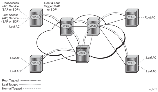
3.4.5.2. Leaf-ac and Root-ac SAPs
Figure 91 shows the terminology used for E-Tree in IETF Draft draft-ietf-l2vpn-vpls-pe-etree and a mapping to SR OS terms.
An Ethernet service access SAP is characterized as either a leaf-ac or a root-ac for a VPLS E-Tree service. As far as SR OS is concerned, these are normal SAPs with either no tag (Null), priority tag, or dot1q or QinQ encapsulation on the frame. Functionally, a root-ac is a normal SAP and does not need to be differentiated from the regular SAPs except that it will be associated with a root behavior in a VPLS E-Tree.
Leaf-ac SAPs have restrictions; for example, a SAP configured for a leaf-ac can never send frames to another leaf-ac directly (local) or through a remote node. Leaf-ac SAPs on the same VPLS instance behave as if they are part of a split horizon group (SHG) locally. Leaf-ac SAPs that are on other nodes need to have the traffic marked as originating “from a Leaf” in the context of the VPLS service when carried on PWs and SAPs with tags (VLANs).
Root-ac SAPs on the same VPLS can talk to any root-ac or leaf-ac.
Figure 91: Mapping PE Model to VPLS Service
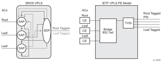
3.4.5.3. Leaf-ac and Root-ac SDP Binds
Untagged SDP binds for access can also be designated as root-ac or leaf-ac. This type of E-Tree interface is required for devices that do not support E-Tree, such as the 7210 SAS, to enable them to be connected with pseudowires. Such devices are root or leaf only and do not require having a tagged frame with a root or leaf indication.
3.4.5.4. Root-leaf-tag SAPs
Support on root-leaf-tag SAPs requires that the outer VID is overloaded to indicate root and leaf. To support the SR service model for a SAP, the ability to send and receive two different tags on a single SAP has been added. Figure 92 shows the behavior when a root-ac and leaf-ac exchange traffic over a root-leaf-tag SAP. Although the figure shows two SAPs connecting VPLS instances 1 and 2, the CLI will show a single SAP with the format:
sap 2/1/1:25 root-leaf-tag leaf-tag 26 create
Figure 92: Leaf and Root Tagging dot1q
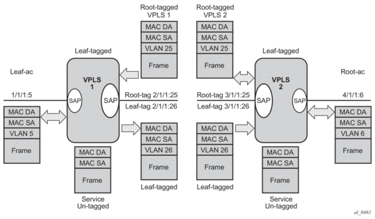
The root-leaf-tag SAP performs all of the operations for egress and ingress traffic for both tags (root and leaf):
- When receiving a frame, the outer tag VID will be compared against the configured root or leaf VIDs and the frame forwarded accordingly.
- When transmitting, the system will add a root VLAN (in the outer tag) on frames with an internal indication of Root, and a leaf VLAN on frames with an internal indication of Leaf.
3.4.5.5. Root-leaf-tag SDP Binds
Typically, in a VPLS environment over MPLS, mesh and spoke-SDP binds interconnect the local VPLS instances to remote PEs. To support VPLS E-Tree, the root and leaf traffic is sent over the SDP bind using a fixed VLAN tag value. The SR OS implementation uses a fixed VLAN ID 1 for root and fixed VLAN ID 2 for leaf. The root and leaf tags are considered a global value and signaling is not supported. The vc-type on root-leaf-tag SDP binds must be VLAN. The vlan-vc-tag command will be blocked in root-leaf-tag SDP-binds.
Figure 93 shows the behavior when leaf-ac or root-ac interfaces exchange traffic over a root-leaf-tag SDP-binding.
Figure 93: Leaf and Root Tagging PW
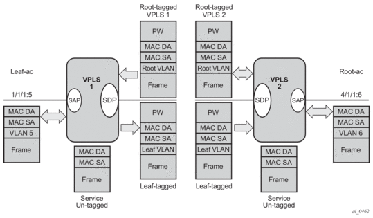
3.4.5.6. Interaction between VPLS E-Tree Services and Other Features
As a general rule, any CPM-generated traffic is always root traffic (STP, OAM, and so on) and any received control plane frame is marked with a root/leaf indication based on which E-Tree interface it arrived at. Some other particular feature interactions are as follows:
- ETH-CFM and E-Tree — ETH-CFM allows the operator to verify connectivity between the various endpoints of the service as well as execute troubleshooting and performance gathering functions. Continuity Checking, ETH-CC, is a method by which endpoints are configured and messages are passed between them at regular configured intervals. When CCM-enabled MEPs are configured, all MEPs in the same maintenance association, the grouping typically along the service lines, must know about every other endpoint in the service. This is the main principle behind continuity verification (all endpoints in communication).Although the maintenance points configured within the E-Tree service adhere to the forwarding rules of the Leaf and the Root, local population of the MEP database used by the ETH-CFM function may make it appear that the forwarding plane is broken when it is not. All MEPs that are locally configured within a service will automatically be added to the local MEP database. However, because of the Leaf and Root forwarding rules, not all of these MEPs can receive the required peer CCM-message to avoid CCM Defect conditions. It is suggested, when deploying CCM enabled MEPs in an E-Tree configuration, these CCM-enabled MEPs are configured on Root entities. If Leaf access requires CCM verification, then down MEPs in separate maintenance associations should be configured. This consideration is only for operators who need to deploy CCM in E-Tree environments. No other ETH-CFM tools query or use this database.
- Legacy OAM commands (cpe-ping, mac-ping, mac-trace, mac-populate, and mac-purge) are not supported in E-Tree service contexts. Although some configuration may result in normal behavior for some commands, not all commands or configurations will yield the expected results. Standards-based ETH-CFM tools should be used in place of the proprietary legacy OAM command set:
- IGMP and PIM snooping for IPv4 work on VPLS E-Tree services. Routers should use root-ac interfaces so that the multicast traffic can be delivered properly.
- xSTP is supported in VPLS E-Tree services; however, when configuring STP in VPLS E-Tree services, the following considerations apply:
- STP must be carefully used so that STP does not block undesired objects.
- xSTP is not aware of the leaf-to-leaf topology; for example, for leaf-to-leaf traffic, even if there is no loop in the forwarding plane, xSTP may block leaf-ac SAPs or SDP binds.
- Since xSTP is not aware of the root-leaf topology either, root ports might end up blocked before leaf interfaces.
- When xSTP is used as a access redundancy mechanism, Nokia recommends that the dual-homed device is connected to the same type of E-Tree AC, to avoid unexpected forwarding behaviors when xSTP converges.
- Redundancy mechanisms such as MC-LAG, SDP bind end-points, or BGP-MH are fully supported on VPLS E-Tree services. However, eth-tunnel SAPs or eth-ring control SAPs are not supported on VPLS E-Tree services.